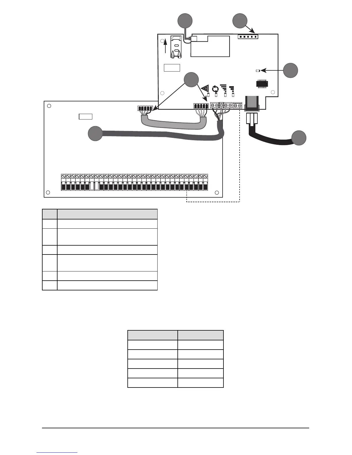
Item Description
1 To External Antenna
2
AUDIO/DEFAULT
Jumper pins 4 and 5 to reset
3 Network Link - Yellow
4
From NID use only CAT5 supervised
maximum cable length 100m (328 feet)
5 RS-232 to third party device
6 RED Wire
Input Ratings:
l +10.8V ~ +12.5VDC
l 90mA(3G2080(R)E)/120mA(TL2803G(R)E) standby;
l 90mA (3G2080(R)E/ LE2080(R)
l 120mA (TL2803G(R)E/TL280LE(R).
l 400mA alarm
DSC Panel minimum power requirements:
l 16.5 VAC 40 VA transformer
l 12 VDC 7Ah battery
5. Install the RS-232 connections (R models only). If using the communicator with a 3rd party device,
wire the connections as per the table below:
Table 3: RS-232 Connections
3rd Party Device Communicator
TX RX+
Unused RX-
RX TX+
Unused TX-
GND GND
6. Perform the following steps for initial power on of the panel with communicator installed:
a. Reconnect the AC power, telephone line, and battery + connector to the panel.
(The communicator and panel will power up together).
b. Observe that the communicator’s red and yellow LEDs are flashing together while it initializes.
The red and yellow LEDs will continue to flash until the communicator has successfully
11
 Loading...