PowerSeries Neo Installation Guide
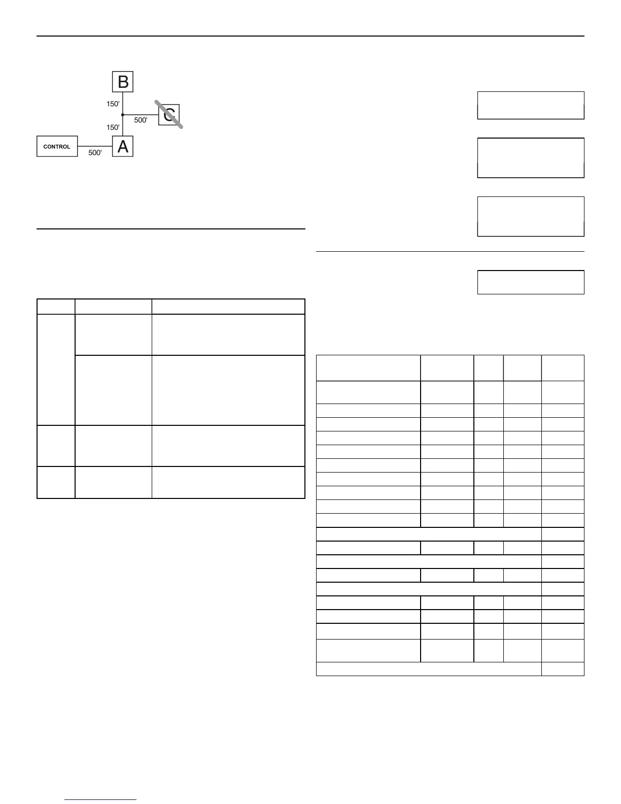
Note: No module can be more than 1,000'/305m (in wire length) from the
panel. Do not use shielded wire for Corbus wiring.
Figure 1-1 Corbus Wiring
Module (A) is wired correctly as it is within 1,000'/305m of the panel, in
wire distance. Module (B) is wired correctly as it is within 1,000'/305m of
the panel, in wire distance. Module (C) is NOT wired correctly as it is
farther than 1,000'/305m from the panel.
Current Ratings
In order for the system to operate properly, the power output of the alarm
controller and power supply modules cannot be exceeded. Use the
following data to ensure that the available current is not exceeded.
Table 1-1 System Output Ratings
Device Output Rating (12VDC)
HS2016
HS2032
HS2064
HS2128
AUX:
700mA . Subtract the listed rating for each
keypad, expansion module and accessory
connected to AUX or Corbus. At least 100mA
must be reserved for the Corbus.
BELL: 700mA. Continuous rating.
2.0A. short term. Available only with standby
battery connected. Not for UL/ULC or EN
certified applications.
HSM2208
AUX:
250mA. Continuous rating. Subtract for each
device connected. Subtract the total load on this
terminal from the alarm panel AUX/Corbus
output.
HSM2108 AUX: 100mA. Subtract for each device connected.
Subtract the total load on this terminal from the
panel AUX/Corbus output.
Alarm Control Panel
AUX - 700mA available for devices connected to the AUX and PGM
terminals, and modules connected to Corbus terminals. At least 100mA
must be reserved for the Corbus.
Alarm Controller Current Calculation
Panel Calculation
Maximum (Standby or Alarm)
AUX (700mA max. including PGMs 1-4)
Corbus (700mA max.)***
PCLink+ (Alt. Com.:125mA)
Total (must not exceed 700mA)
*** See "Corbus Current Calculation Chart" on page 3.
For UL, ULC and Commercial Listed applications, the total standby and
alarmcurrent cannot exceed 700mA.
Table 1-2 Corbus Current Calculation Chart
Item Current
(mA)
x Quantity Total
(mA)
HS2016/HS2032
/HS2064/HS2128
85 X 1 85
HS2LCD 105 x
HS2ICN 105 x
HS2LED 105 x
HS2LCDP 105 x
HS2ICNP 105 x
HS2LCDRF 105 x
HS2ICNRF 105 x
HS2ICNRFP 105 x
HS2TCHP 160 x
Current required for connected devices =
HSM2108* 30 x
AUXoutput current of HSM2108
HSM2208* 40 x
AUXoutput current of HSM2208
HSM2300/2204* 35 x
HSM2HOSTx 35 x
HSM2955** x
3G208(R)/TL2803G(R)/TL280
(R)
125 (PCLINK) x
Total Corbus Current =
*These units draw current from the Corbus to power devices external to
the module. This current must be added to the total Corbus current. See
manufacturer's specifications for the current draw of each device.
** For HSM2955 current draw refer to HSM2955 installation manual.
- 3 -

 Loading...