DSE Model 521 Remote Start Engine Management System - Operators Manual
DSE 521 ISSUE 4 4/4/02 MR 11
4. ELECTRICAL CONNECTIONS
Connections to the 521 Module are via plug and sockets.
4.1 CONNECTION DETAILS
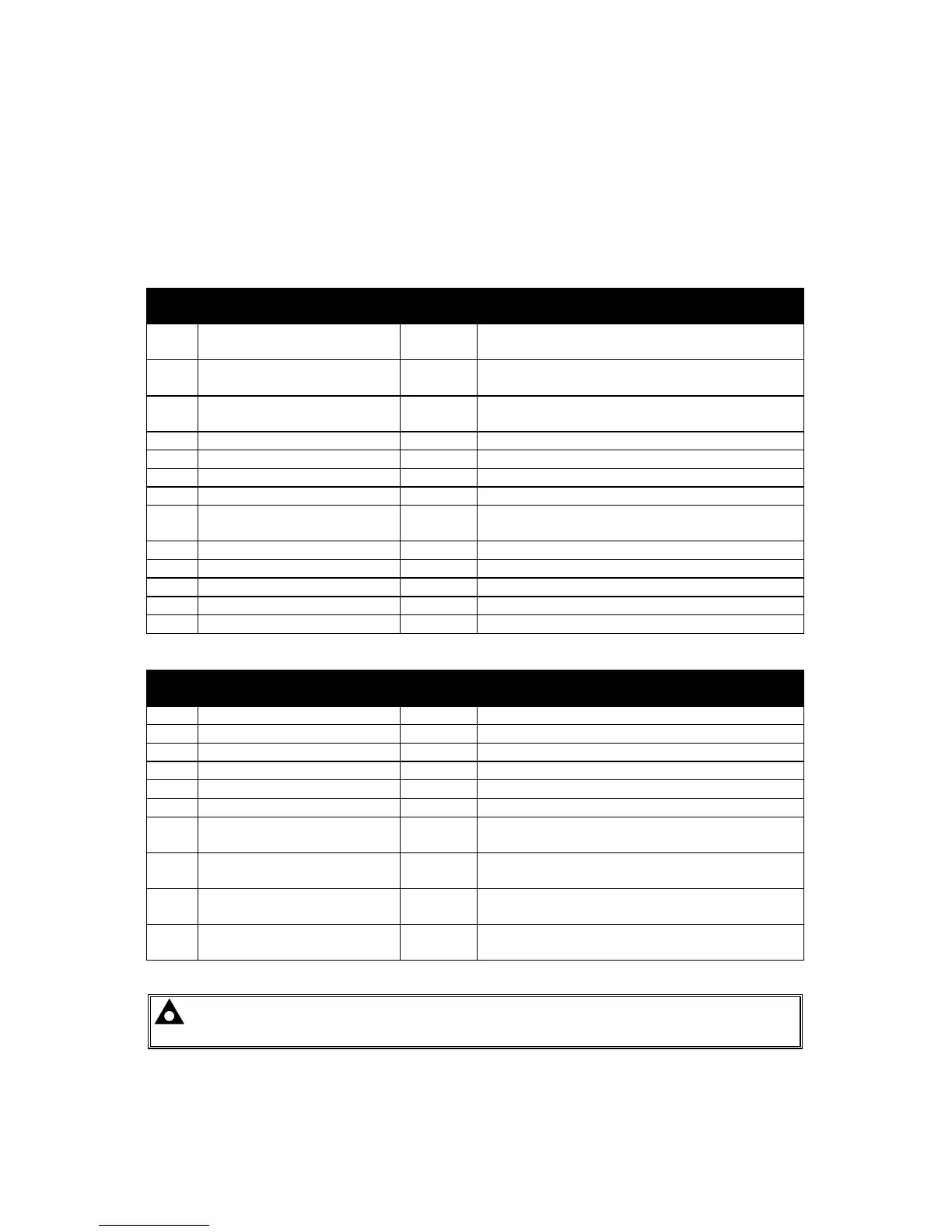
The following describes the connections and recommended cable sizes to the 2 plugs and sockets
on the rear of the
521 Module. See rear panel layout FIG 5.
PLUG “A” 13 WAY
PIN
No
DESCRIPTION CABLE
SIZE
NOTES
1 DC Plant Supply Input
(-ve)
2.5mm
2 DC Plant Supply Input
(+ve)
2.5mm (Recommended Fuse 18A)
3 Emergency Stop Input 2.5mm Plant Supply +ve. Also supplies fuel & start
outputs.(Recommended Fuse 32A)
4 Fuel relay Output 2.5mm Plant Supply +ve from pin 3. 16 Amp rated.
5 Start relay Output 2.5mm Plant Supply +ve from pin 3. 16 Amp rated.
6 Auxiliary Output relay 1 1.0mm Plant Supply +ve. 5 Amp rated.
7 Auxiliary Output relay 2 1.0mm Plant Supply +ve. 5 Amp rated.
8 Charge Fail Input/
Excitation Output
1.0mm Must NOT be connected to plant supply -ve
if not used.
9 Low Oil Pressure Input 0.5mm Switch to -ve
10 High Engine Temp Input 0.5mm Switch to -ve
11 Auxiliary Input 1 0.5mm Switch to -ve
12 Auxiliary Input 2 0.5mm Switch to -ve
13 Remote Start Input 0.5mm Switch to -ve
PLUG “B” 10 WAY
PIN
No
DESCRIPTION CABLE
SIZE
NOTES
14 Alternator Input L1 1.0mm Do not connect if not used. (2A Fuse)
15 Alternator Input N 1.0mm Do not connect if not used.
16 DO NOT USE Ensure no connection is made to this pin.
17 Auxiliary Output 3 1.0mm Plant Supply +ve. 5 Amp rated.
18 Auxiliary Input 3 0.5mm Switch to -ve
19 Auxiliary Input 4 0.5mm Switch to -ve
20 Magnetic Pickup Input
(+ve)
0.5mm Connect to Magnetic Pickup device
21 Magnetic Pickup Input
(-ve)
0.5mm Connect to Magnetic Pickup device
22 Tachometer Output (+ve) 0.5mm Optional, specified on ordering.
Tachometer must be completely isolated.
23 Tachometer Output (-ve) 0.5mm Optional, specified on ordering.
Tachometer must be completely isolated.
NOTE:- Screened cable must be used for connecting the Magnetic Pickup, ensuring
that the screen is earthed at one end ONLY.