DSE Model 521 Remote Start Engine Management System - Operators Manual
DSE 521 ISSUE 4 4/4/02 MR
18
11. APPENDIX
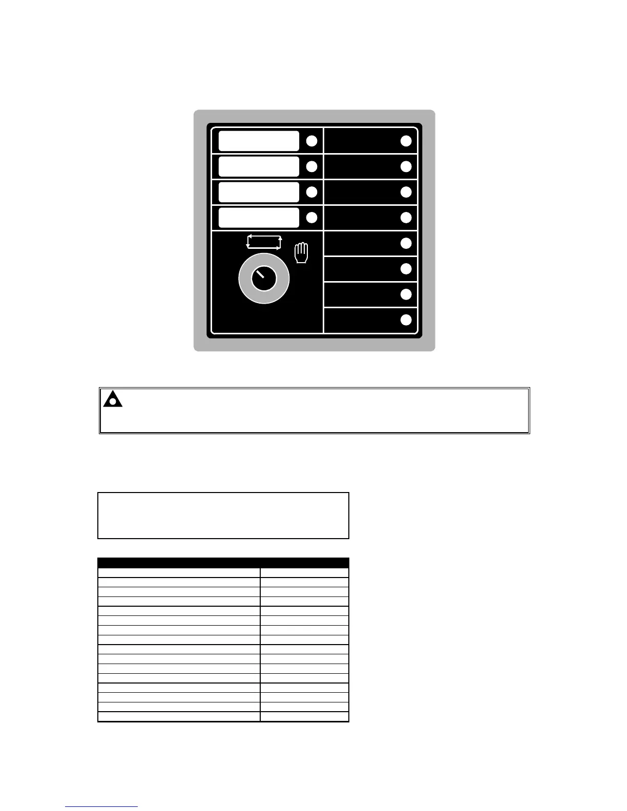
11.1 LED IDENTIFICATION DIAGRAM
O
AUTO
Deep Sea Electronics plc
Model 521
LED 11
LED 10
LED 9
LED 8
LED 7
LED 6
LED 5
LED 4
LED 3
LED 2
LED 1
FIXED
FIG 6
Note:- The Software disk supplied with the Calibration Interface (808) contains a
Microsoft Word document for the automatic creation of suitable label inserts for the
Auxiliary LED’s.
11.2 FACTORY DEFAULT CONFIGURATION
The 521 module when shipped contains the following configuration, allowing it to be used as a
standard module if no configuration interface is available.
P52x Configuration
Title: Standard default settings factory set
Created by: Miles Revell
Date: 4 March 1997
Filename: P521A
MISCELLANEOUS ITEMS
Item Value
Start attempts 3
Alternator frequency input present Yes
Nominal frequency 50Hz
Alternator poles 4
Magnetic pickup input present No
Flywheel teeth 118
Nominal RPM 1500
Lamp test enabled No
Start button None
Stop button None
Safety on delay time termination Premature
Load transfer mode Normal
Pre-heat mode Normal
Tachometer full scale current 0.5mA
Tachometer full scale RPM 2500
Electrical trip enabled No