DSE Model 521 Remote Start Engine Management System - Operators Manual
DSE 521 ISSUE 4 4/4/02 MR
12
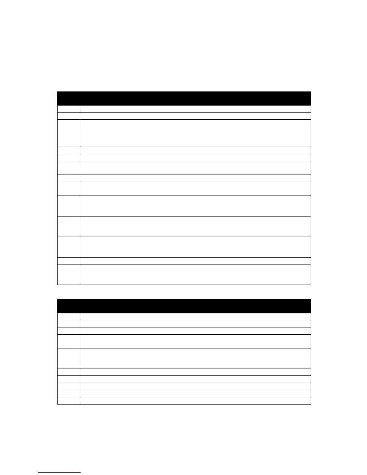
4.2 CONNECTOR FUNCTION DETAILS
The following describes the functions of the 2 connectors on the rear of the module. See rear panel
layout
FIG 5.
PLUG “A” 13 WAY
PIN
No
DESCRIPTION
1 DC Supply -ve. System DC negative input. (Battery Negative).
2 DC Supply +ve. System DC positive input. (Battery Positive).
3 Emergency Stop input. Internally linked to Starter and Fuel outputs. If this input is
not connected to positive the module will be locked out, and if the engine is
running will shutdown immediately. Positive Supply also removed from Starter and
Fuel therefore only a single pole Emergency Shutdown button is required.
4 Fuel Relay output. Plant Supply +ve from pin 3. Used to control the fuel solenoid.
5 Starter Relay output. Plant Supply +ve from pin 3. Used to control the Starter Motor.
6 Auxiliary Relay output 1. Plant Supply +ve. Configurable output, see Calibration
Manual for options available.
7 Auxiliary Relay output 2. As for Auxiliary output 1 (Pin No 6).
8 Charge Fail input / Excitation output. Supplies excitation to the Plant Battery
Charging Alternator, also an input for the Charge Fail detection circuitry.
9 Low Oil Pressure input. This is a negative switched input, it is possible to calibrate
the input to be a normally closed signal or a normally open signal. This input is
used to signal to the module that the oil pressure is low.
10 High Engine Temperature input. This is a negative switched input, it is possible to
calibrate the input to be a normally closed signal or a normally open signal. This
input is used to signal to the module that the engine temperature is high.
11 Auxiliary input 1. This is a negative switched configurable input, see Calibration
Manual for options available. It is possible to configure the input to be a normally
closed signal or a normally open signal.
12 Auxiliary input 2. As for Auxiliary input 1 (Pin 11).
13 Remote Start input. This is a negative switched input which will start the generator
when Auto is selected. It is possible to configure the input to be a normally open
signal or a normally closed signal.
PLUG “B” 10 WAY
PIN
No
DESCRIPTION
14 Alternator Input L1. Used for Alternator speed sensing.
15 Alternator Input N. Used for Alternator speed sensing.
16 DO NOT USE
17 Auxiliary Relay output 3. Plant Supply +ve. Configurable output, see Calibration
Manual for options available.
18 Auxiliary input 3. This is a negative switched configurable input, see Calibration
Manual for options available. It is possible to configure the input to be a normally
closed signal or a normally open signal.
19 Auxiliary input 4. As for Auxiliary input 3 (Pin 18).
20 Magnetic Input +ve. An AC signal from the magnetic pickup +ve for speed sensing.
21 Magnetic Input -ve. An AC signal from the magnetic pickup -ve for speed sensing.
22 Tachometer output +ve. 0.5 or 1.0 mA Tachometer can be used.
23 Tachometer output -ve. ---------------------- “ ----------------------------