ADJUSTABLE PARAMETERS (Configuration editor)
(Factory default settings are shown in bold italicised text)
Parameter as shown on display
Language English - Others
LCD Page Timer
hh:mm:ss (5m)
Auto Scroll Delay
1s - 1hr (2s)
Default Config
Default Config
Oil Pressure Low Shutdown
0bar - 9.97bar (1.03bar)
Coolant Temperature High Shutdown 2ºC - 140ºC (95ºC)
Start Delay Timer
0 - 10hr (5s)
Pre Heat Timer
0 - 5m (0s)
Crank Duration Timer
0 - 1m (10s)
Crank Rest Timer
0 - 1m (10s)
Safety On Delay 0 - 1m (10s)
Smoke Limiting
0 - 15m (0s)
Smoke Limiting Off
0 - 1m (0s)
Warm Up Timer
0 -1hr (0s)
Cool Down Timer
0 - 1hr (1m)
Speed Low Shutdown Active, Inactive
Speed Low Shutdown
0RPM - 6000RPM (1270RPM)
Speed High Shutdown
0RPM - 6000RPM (1740RPM)
Speed Overshoot Delay
0-10s (2s)
Speed Overshoot
0% - 10% (0s)
Fail To Stop Delay 0 - 2m (30s)
Battery Voltage Low Warning
Active, Inactive
Battery Low Voltage
0V – 40V (10V)
Battery voltage Low Warning Delay
0 - 24hr (1m)
Battery Voltage High Warning
Active, Inactive
Battery Voltage High Warning Delay 0V - 24hr (1m)
Battery Voltage High Warning
0V – 40V (30V)
Charge Alternator Failure Warning
Active, Inactive
Charge Alternator Failure Warning
0V – 39V (6V)
Charge Alternator Failure Warning Delay
0 - 24hr (5s)
Charge Alternator Failure Shutdown Active, Inactive
Charge Alternator Failure Shutdown
0V – 5.9V (4.0V)
Charge Alternator Failure Shutdown Delay
0 - 24hr (5s)
Voltage Low Shutdown
50V – 360V (184V)
Voltage Nominal
50V – 276V (230V)
Voltage High Shutdown 231V – 360V (277V)
Frequency Low Shutdown
0Hz - 75Hz (43Hz)
Frequency Nominal
0Hz - 75Hz (50Hz)
Frequency High Shutdown
0Hz - 75Hz (58Hz)
Full Load Rating
5A – 6000A (500A)
Delayed Over Current Active, Inactive
Delayed Over Current
50% - 120% (100%)
AC System Single Phase, 2 Wire
3 Phase, 4 Wire
3 Phase, 4 Wire3 Phase, 4 Wire
3 Phase, 4 Wire
2 Phase, 3 Wire (L1 & L3)
3 Phase, 4 Wire (Delta)
2 Phase, 3 Wire (L1 & L2)
CT Primary
5A - 6000A (600A)
Generator Transient Delay
0 - 10m (0.7s)
ront Panel Configuration Editor
(Factory default settings are shown in bold italicised text)
Section
Parameter as shown on display
Values
MAINS Voltage Low Trip 50V – 360V (184V)
Voltage High Trip 50V – 360V (276V)
Frequency Low Trip 0Hz - 75Hz (45Hz)
Frequency High Trip 0Hz - 75Hz (55Hz)
Mains Transient Delay 0 - 30s (2s)
Return Delay 0 - 1hr (30s)
Mains Transfer Time 0 - 10m (0.7s)
TIMERS
LCD Page Timer
hh:mm:ss (5m)
Auto Scroll Delay
1s - 1hr (2s)
Pre Heat Timer 0 - 5m (0s)
Crank Duration Timer
0 - 1m (10s)
Crank Rest Timer
0 - 1m (10s)
Safety On Delay
0 - 1m (10s)
Smoke Limiting
0 - 15m (0s)
Smoke Limiting Off
0 - 1m (0s)
Warm Up Timer
0 -1hr (0s)
Cool Down Timer
0 - 1hr (1m)
Fail To Stop Delay
0 - 2m (30s)
Battery voltage Low Warning Delay
0 - 24hr (1m)
Battery Voltage High Warning Delay 0V - 24hr (1m)
Return Delay 0 - 5hr (30s)
Generator Transient Delay 0.1s - 2m (30s)
Mains Transient Delay 0 - 30s (2s)
Mains Transfer Time 0 - 10m (0.7s)
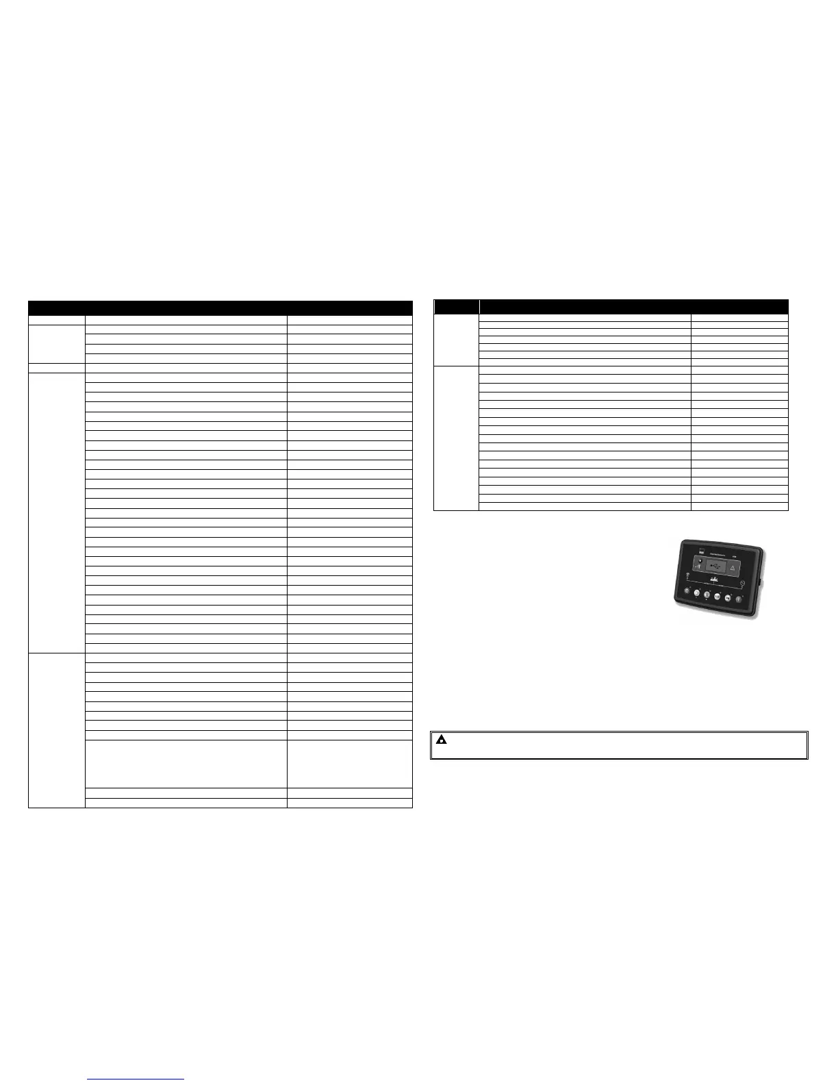
DIMENSIONS AND MOUNTING
DIMENSIONS
216mm x 158mm x 42mm
(8.5” x 6.2” x 1.6”)
PANEL CUTOUT
182mm x 137mm
(7.2” x 5.4”)
1.1.1 WEIGHT
510g (0.51kg)
1.1.2 FIXING CLIPS
The module is held into the panel fascia using the supplied fixing clips.
• Withdraw the fixing clip screw (turn anticlockwise) until only the pointed end is protruding from the clip.
• Insert the three ‘prongs’ of the fixing clip into the slots in the side of the 6000 series module case.
• Pull the fixing clip backwards (towards the back of the module) ensuring all three prongs of the clip are
inside their allotted slots.
• Turn the fixing clip screws clockwise until they make contact with the panel fascia.
• Turn the screws a little more to secure the module into the panel fascia. Care should be taken not to over
tighten the fixing clip screws.
NOTE:- In conditions of excessive vibration, mount the panel on suitable
anti-vibration mountings.

 Loading...


