■■■■■■■■■■■■■■■■■■■■■■■■■■■■■■■■■■■■■■■■■■■■■■■■■■■■■■■■■■■■■■■■■■■■■■■■■■■■
▼
Signal Connection to External Devices
DS1104 Hardware Installation and Configuration March 2004
121
▲
■■■■■■■■■■I
▲■■■■■■■■■■■■■■■
Input Circuit and Electrical Characteristics
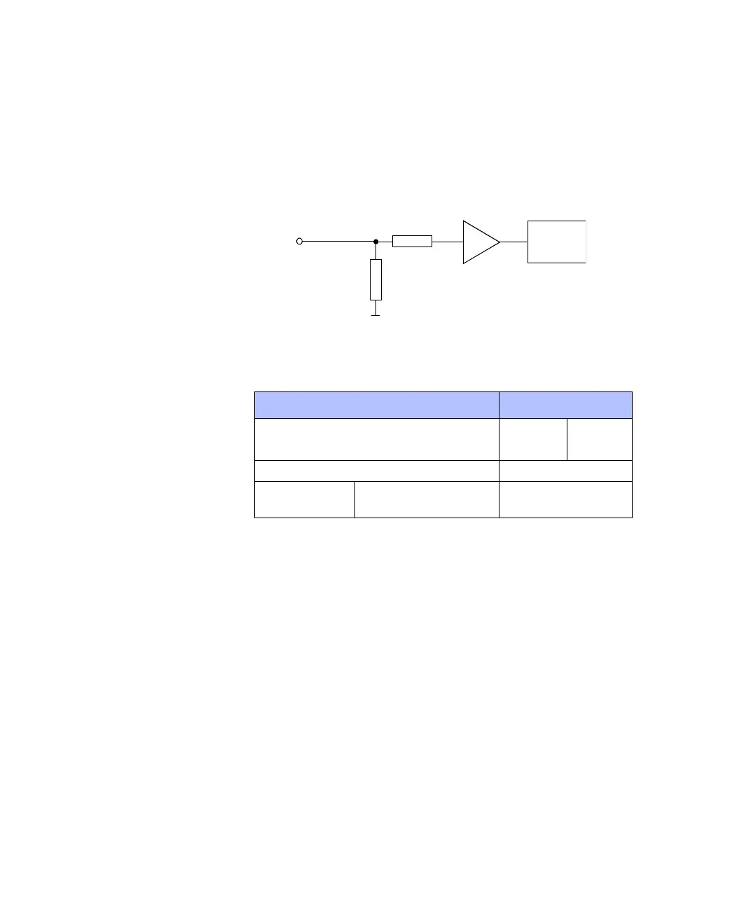
Input circuit The following illustration is a simplified diagram of the input circuitry
of the ADCs.
Electrical characteristics The analog inputs are single-ended bipolar inputs with the following
characteristics.
Notes and Tips on Signal Conditioning
The following notes and tips are intended to help you achieve
optimum results using the ADCs.
Noise, crosstalk and inductive effects can degrade the signal and lead
to incorrect results if you do not perform the following correctly:
■ Grounding and Shielding on page 147
■ Avoiding Crosstalk on page 151
■ Wiring Up External Devices on page 152
R
in,amp
> 10 M
Ω
ADC
1 k
Ω
ADCHx
1 MΩ
R
in
≈
1 M
Ω
Parameter Value
Min. Max.
Input voltage –10 V +10 V
Input resistance Approx. 1 MΩ
SNR (signal-to-
noise ratio)
• 16-bit muxed ADCs
• 12-bit parallel ADCs
• > 80 dB
• > 65 dB