Connector Pinouts and LEDs
▲
■■■■■■■■■■■■■■■■■■■■■■■■■■■■■■■■■■■■■■■■■■■■■■■■■■■■■■■■■■■■■■■■■■■■■■■■■■■■■■■■■■■■■■■■■
DS1104 Hardware Installation and Configuration March 2004
I■■■■■■■■■■■■■
▼
96
■■■■■■■■■■■■■■■▼
Incremental Encoder Interface
Connectors (CP19, CP20)
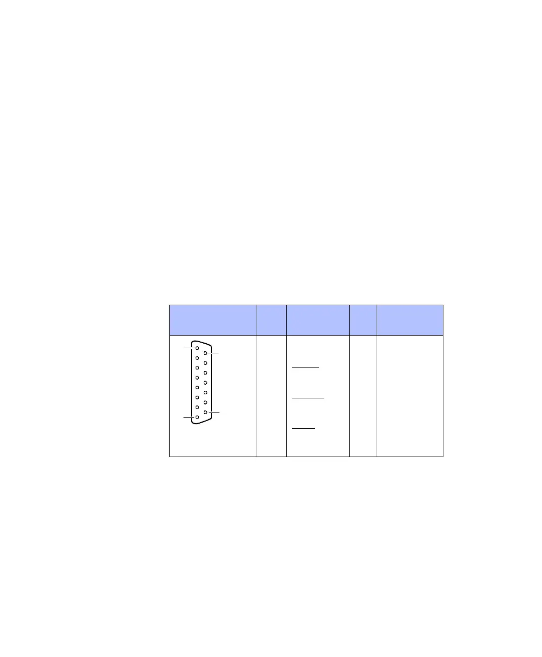
The incremental encoder interface connectors CP19 and CP20 are
15-pin, female Sub-D connectors located on the front of the
connector panel. Each of the connectors provides the signals for one
of the two available incremental encoder channels.
Pinout Because the pin numbering used for Sub-D connectors is not
standardized, the following figure shows the numbering scheme used
(front view).
C
Do not rely on the numbers written on Sub-D connectors.
x corresponds to the two available incremental encoder channels:
Channel 1 is connected to CP19 (x = 1), channel 2 is connected to
CP20 (x = 2).
N
For the CP1104 and CLP1104 Connector Panels, the total load of all
connector pins that provide access to the PC power supply must not
exceed 500 mA (CP1104) or 400 mA (CLP1104).
Connector (CP19,
CP20)
Pin Signal Pin Signal
1 VCC (+5 V)
2 PHI0(x) 9 VCC (+5 V)
3PHI0(x)
10 GND
4 PHI90(x) 11 GND
5 PHI90(x)
12 GND
6 IDX(x) 13 GND
7IDX(x)
14 GND
8GND 15GND
1
8
15
9