■■■■■■■■■■■■■■■■■■■■■■■■■■■■■■■■■■■■■■■■■■■■■■■■■■■■■■■■■■■■■■■■■■■■■■■■■■■■
▼
Signal Connection to External Devices
DS1104 Hardware Installation and Configuration March 2004
145
▲
■■■■■■■■■■I
▲■■■■■■■■■■■■■■■
Using the ST1PWM Pin
The ST1PWM pin is lead to the interrupt controller of the DS1104, so it
is possible to generate interrupts that are synchronous to PWM signal
generation. You can also use the pin as a further external interrupt
input (user interrupt). In this case the ST1PWM pin has to be
configured as an input (using RTLib1104).
Strobing I/O In addition, you can use the ST1PWM pin for strobing the I/O (ADCs,
DACs and incremental encoder signals). The required trigger signal can
be either generated by the slave DSP or driven externally. In the second
case the ST1PWM pin has to be configured as an input or the slave
DSP must be in reset mode.
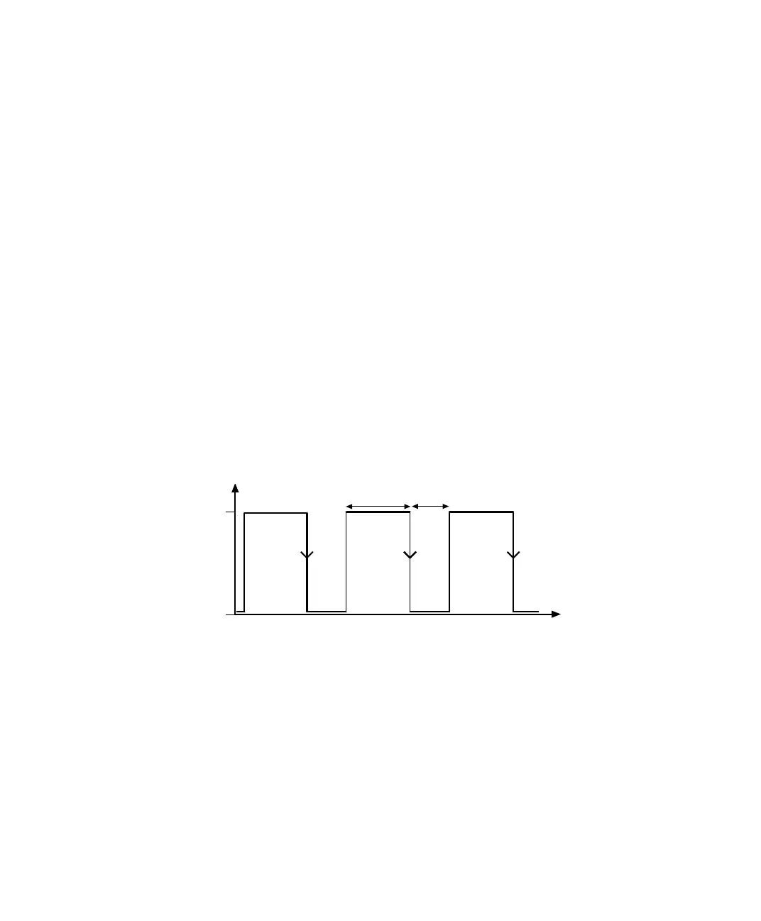
Recognizing signals at
the ST1PWM pin
To allow the interrupt controller to recognize an incoming signal at the
ST1PWM pin (PWM interrupt, external interrupt or trigger for
strobing), the interrupt signal must be kept high for at least 1 µs. The
interrupt is activated by the high to low transition of the signal. The
signal must remain low for at least 100 ns after the transition.
high
low
t
T
high
T
low
T
high min
:
1
µ
s
T
low min
: 100 ns