■■■■■■■■■■■■■■■■■■■■■■■■■■■■■■■■■■■■■■■■■■■■■■■■■■■■■■■■■■■■■■■■■■■■■■■■■■■■
▼
Signal Connection to External Devices
DS1104 Hardware Installation and Configuration March 2004
149
▲
■■■■■■■■■■I
▲■■■■■■■■■■■■■■■
Grounding Signals
Do not use a ground line for more than one purpose. A grounding
scheme has to be evaluated based on its AC current flow and not on
its DC behavior. The DC resistance of a cable has only minor impact.
Cable inductance plays a major role.
Avoiding ground loops
and ground bounces
To avoid ground loops and ground bounces, use separate signal return
(ground) lines for all connected sensors and actuators.
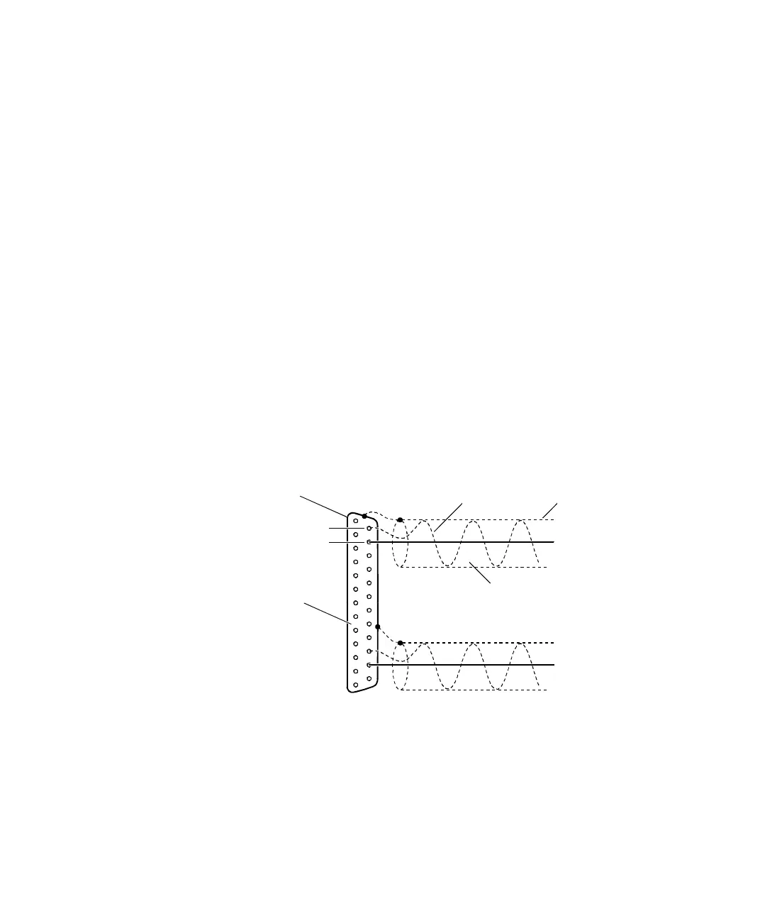
Each signal should have its own return line. The best results can be
achieved with a shielded twisted pair cable. A twisted pair cable has
the lowest inductance.
On the sensor/actuator side, connect one of the twisted wires to the
signal and the other one to ground. On the board side, connect the
first wire to the input/output and the second one to ground. The
shield should be connected to the housing of the sensor/actuator and
to the metal shell of the board connector. Do not connect the shield to
ground anywhere.
If not enough ground pins are available at the connector, several
return lines can be attached to a common ground pin. However, this
common ground lead should be kept as short as possible to reduce
ground line inductance.
Signal return line A
Signal A
Shield
Signal B
Metal shell
Shielded twisted pair cable
I/O pin
GND pin
I/O connector