A
B
C
D
E
F
G
H
L
M
N
P
Comandi - Dispositivi
Controls - Devices
sezione / section
F 4
17Monster 400/620 - M.Y. 2004 - edizione/edition 00
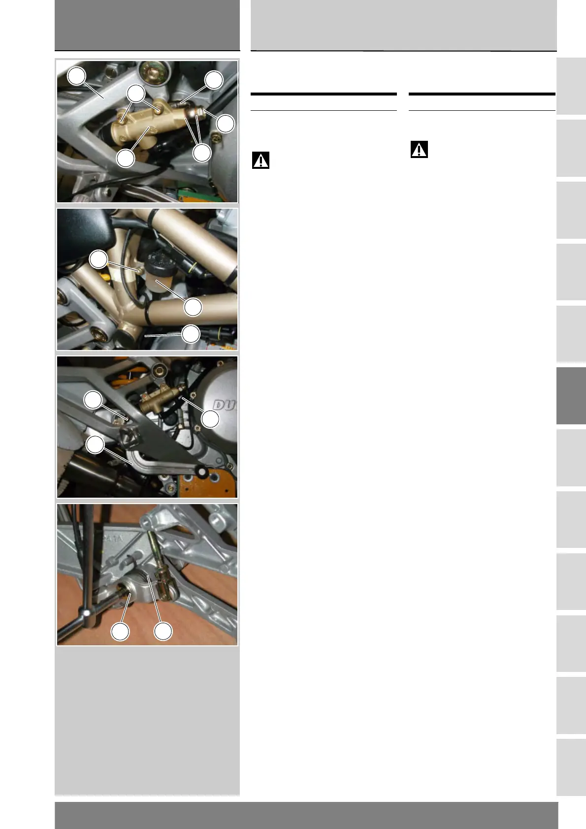
Smontaggio pompa freno
posteriore
Attenzione
La casa costruttrice della
pompa freno, considerando
l’importanza in termini di sicurezza
che riveste questo componente,
suggerisce di non intervenire in
nessun modo all’interno della pompa.
Una revisione non eseguita
correttamente può mettere in serio
pericolo l’incolumità del pilota.
Le operazioni di sostituzione si
devono limitare; alla leva di comando,
al gruppo serbatoio con relativi
componenti di fissaggio e al fissaggio
pompa.
Svitare le viti (18) di fissaggio pompa
freno idraulico posteriore (17) dalla
piastra porta pedana (A).
Svitare dalla pompa (17), la vite
speciale (1), recuperando le due
rondelle (2).
Svitare la vite (20), facendo attenzione
alla rosetta (25) e rimuovere il
serbatoio olio (22), completo di tubo
(16).
Rimuovere la piastra porta pedana
(Sez. H 4).
Svitare il perno (5) di fissaggio leva
comando freno posteriore alla staffa
portapedana e sfilare la molla (6), la
leva pedale completa (9) e la rosetta
(12).
Operazioni Rif. Sez.
Svuotare l’impianto
frenante
D 4
Removing the rear brake
master cylinder
Warning
Critical safety components. The
brake master cylinder manufacturer
recommends that you do not attempt
to service the internal components of
the brake master cylinder. Incorrect
overhaul of these critical safety
components can endanger rider
safety.
Maintenance operations on these
units are limited to replacing: control
lever, reservoir unit and reservoir and
cylinder fasteners.
Unscrew the retaining screws (18) of
the rear brake cylinder (17) from the
footpeg plate (A).
Unscrew the special screw (1) from
the brake cylinder (17) and collect the
two washers (2).
Unscrew the screw (20), making sure
to collect the washer (25). Remove
the reservoir (22) together with the
hose (16).
Remove the footpeg plate (Sect. H 4).
Withdraw the retaining pin (5)
securing the rear brake lever to the
footpeg bracket. Remove the spring
(6), the complete brake lever (9) and
the washer (12).
Operations Ref.Sect.
Drain the brake circuit D 4
17
18
1
3
A
2
20
22
16
11
16
9
6
5
 Loading...