A
B
C
D
E
F
G
H
L
M
N
P
Mototelaio
Frame
sezione / section
H 2
9Monster 400/620 - M.Y. 2004 - edizione/edition 00
Inserire il perno di sterzo, all'interno
del cannotto portandolo assialmente
in appoggio.
Installare il gruppo base di sterzo sul
telaio.
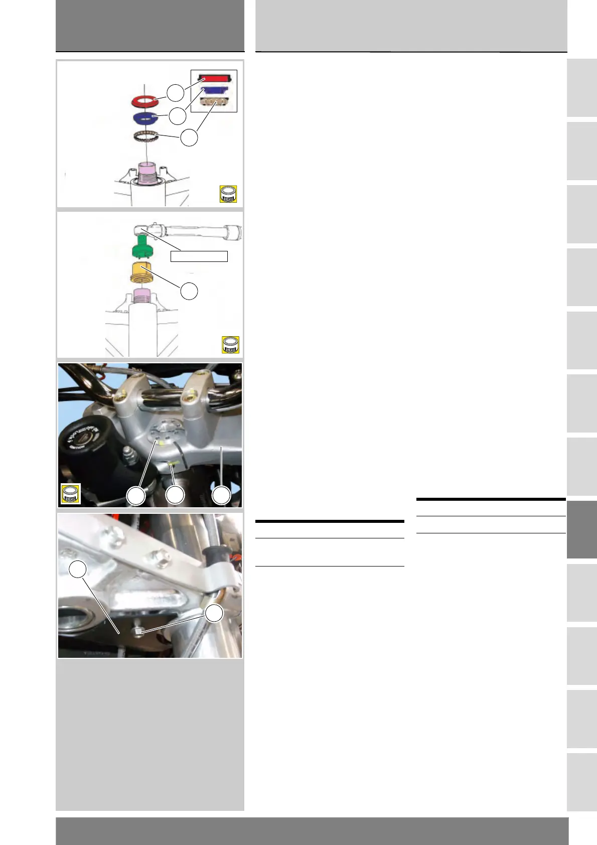
Inserire sull'anello esterno superiore
(C) del telaio, la corona di sfere (B)
opportunamente ingrassata.
Montare sul cannotto l’anello interno
(A) del cuscinetto superiore (5), con la
parte di diametro maggiore, rivolta
verso l'alto.
Montare l'anello di tenuta (4) con la
superficie piana verso l'alto.
Applicare grasso sulla ghiera (3).
Avvitare manualmente la ghiera (3) di
registro fino a portarla in battuta
sull'anello di tenuta (4).
Posizionare sulla ghiera (3) la bussola
speciale cod. 88713.1058 sulla quale
applicare la chiave dinamometrica.
Serrare la ghiera di registro (3) alla
coppia prescritta (Sez. C 3).
Installare la testa di sterzo (2) sulla
ghiera (3) facendo corrispondere le
sedi degli steli forcella con le
corrispondenti sulla base di sterzo.
Riposizionare gli steli forcella nel
modo descritto alla Sez. G 2.
Ingrassare la vite (1).
Bloccare la vite (1) sulla testa di sterzo
alla coppia prescritta (Sez. C 3).
Se è stato rimosso il paraspruzzi (13),
applicare frenafiletti alle viti (10) e
serrare le viti alla coppia prescritta
(Sez. C 3).
Operazioni Rif Sez.
Rimontare gli steli
forcella
G 2
Rimontare il manubrio H 1
Fit steering shaft into steering tube
and push until it becomes fully seated
axially.
Install the bottom yoke assembly to
the frame.
Grease the ball ring (B) and fit it to the
top outer ring (C) of the frame.
Fit the inner ring (A) of the upper
bearing (5) onto the steering shaft; its
larger side should be face up.
Fit the oil seal (4) with the flat face
facing upwards.
Grease the ring nut (3).
Screw the ring nut (3) finger-tight until
it contacts the oil seal (4).
Position the special bush no.
88713.1058 onto the ring nut (3) and
then fit the torque wrench on the
bush.
Tighten the adjusting ring nut (3) to
the specified torque (Sect. C 3).
Install the steering head (2) to the ring
nut (3) so that the fork leg clamp
holes match those in the bottom
yoke. Position the fork legs as
specified under Sect. G 2.
Grease the screw (1).
Tighten the screw (1) on steering
head to the specified torque (Sect.C
3).
If removed, fit the splash guard (13),
apply threadlocker to the screws (10)
and tighten them to the specified
torque (Sect. C 3).
Operations See Sect.
Refit the fork legs G 2
Refit the handlebar H 1
B
A
4
A
D
88765.1058
3
3
1
2
B
10
13
 Loading...