A
B
C
D
E
F
G
H
L
M
N
P
Impianto di alimentazione / Scarico
Fuel system / Exhaust system
sezione / section
L 4.2
15Monster 400 - 620 Aggiornamento/Update - M.Y. 2006 - edizione/edition 00
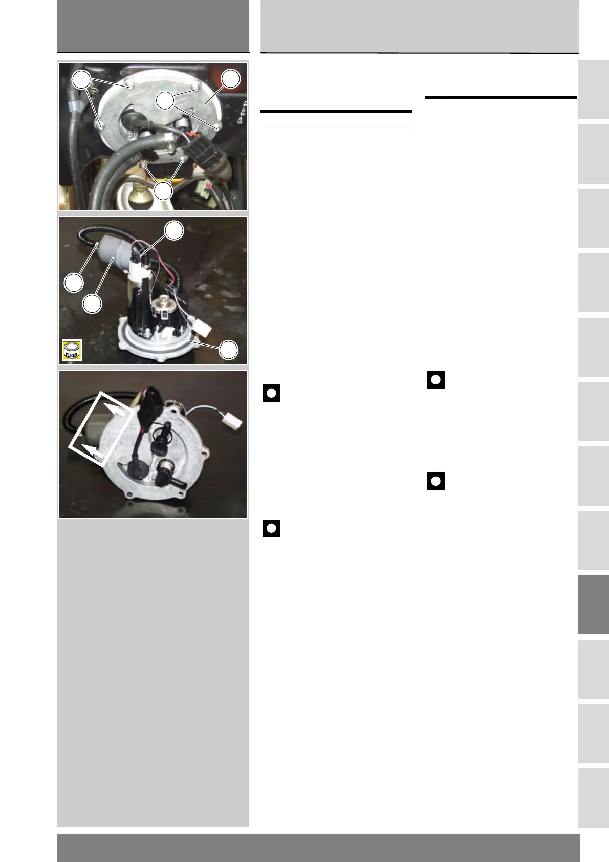
Sostituzione filtro
benzina per serbatoio
rotazionale
Svitare le sei viti (3) di fissaggio
flangia (2) del serbatoio. Rimuoverne
tre e lasciare le altre tre in posizione a
croce, per aiutarsi a sollevare la
flangia (2).
Rimuovere la flangia (2) completa dal
serbatoio.
Sganciare con apposito attrezzo
commerciale i collari (7) e (9) in
corrispondenza del filtro benzina (10).
Sfilare il filtro dalle tubazioni di
collegamento e sostituirlo.
Prima del rimontaggio pulire
accuratamente tutti gli elementi da
eventuali depositi o incrostazioni.
Importante
Quando si installa il filtro (10)
nuovo disporlo con la freccia,
stampigliata sul contenitore esterno,
rivolta verso la flangia.
Ingrassare opportunamente l’OR di
tenuta nuovo (6) sulla flangia e
procedere nel rimontaggio
eseguendo le stesse operazioni dello
smontaggio nell’ordine inverso.
Importante
Fare attenzione
all’orientamento della flangia nel
serbatoio: deve presentare le frecce e
la scritta FRONT rivolta verso il senso
di marcia del veicolo.
Serrare le viti (3) alla coppia prescritta
(Sez. C 3).
Operazioni Rif. Sez.
Rimuovere il serbatoio L 2
Replacing the fuel filter -
plastic fuel tank
Release the six retaining screws (3) of
the fuel tank flange (2). Remove one
every two screws. The three screws
left in place will help lift off the flange
(2).
Remove the complete flange (2) from
the reservoir.
Release the clamps (7) and (9) at the
fuel filter (10) with the suitable tool
available on the market.
Detach the filter from the connecting
hoses and fit a new filter.
On refitting, clean off any build-up or
scale accumulation from all
components.
Caution
Position the new filter (10) with
the arrow stamped on the outer
casing pointing towards the flange.
Change the flange O-ring (6). Grease
the new O-ring and reverse the
removal procedure to refit.
Caution
Make sure to fit the flange in
the correct mounting position: the
arrows and FRONT must be pointing
in the direction of travel of the
vehicle.
Tighten the screws (3) to the
specified torque (Sect. C 3).
Operations Ref. Sect.
Remove the fuel tank L 2
3
2
3
3
9
A
10
6
7
F
R
O
N
T
 Loading...