A
B
C
D
E
F
G
H
L
M
N
P
Impianto di alimentazione / Scarico
Fuel system / Exhaust system
sezione / section
L 10
36 Monster 400/620 - M.Y. 2004 - edizione/edition 00
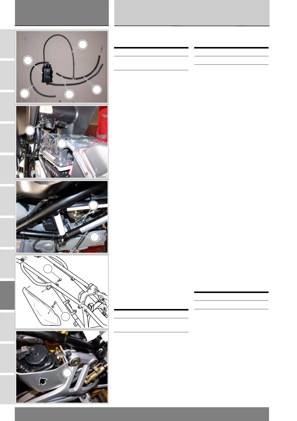
Smontaggio Filtro
Canister
Allentare la fascetta (13) di fissaggio
tubo collegamento Filtro Canister (9)
a serbatoio e scollegare il tubo (12)
dal serbatoio.
Allentare le fascette (18) di fissaggio
delle tubazioni collegamento Filtro
Canister (9) ai collettori cilindro oriz-
zontale e verticale.
Scollegare la tubazione (21) di colle-
gamento Filtro Canister (9) a cilindro
verticale.
Scollegare la tubazione (16) di colle-
gamento Filtro Canister (9) a cilindro
orizzontale.
Rimuovere il fianchetto laterale
destro di copertura svitando le viti (A)
di fissaggio.
Sollevare il Filtro Canister (9) e sbloc-
carlo dal piastrino (6).
Rimontaggio Filtro
Canister
Nel rimontaggio eseguire le
operazioni in ordine inverso a quelle
eseguite nella fase di smontaggio
facendo attenzione a serrare le viti (A)
alla coppia serraggio prescritta (Sez.
C3).
Operazioni Rif. Sez.
Sollevare il serbatoio
carburante
L 2
Sollevare la sella E 3
Operazioni Rif. Sez.
Rimontare il serbatoio
carburante
L 2
Rimontare la sella E 3
Removing the Canister
filter
Loosen the clamp (13) securing the
Canister filter (9) connection hose to
the tank and disconnect the hose
(12).
Loosen clamps (18) securing the
Canister Filter (9) connection hoses to
horizontal and vertical cylinder
manifolds.
Disconnect hose (21) connecting the
Canister Filter (9) to the vertical
cylinder.
Disconnect hose (16) connecting the
Canister Filter (9) to the horizontal
cylinder.
Loosen the screws (A) and remove
the right-hand side body panel.
Lift the Canister Filter (9) and release
it from the plate (6).
Refitting the Canister
Filter
Refitting is a reversal of the removal
procedure, tighten the screws (A) to
the specified torque (Sect. C3).
Operations Ref.Sect.
Lift the fuel tank L 2
Lift the seat E 3
Operations Ref.Sect.
Refit the fuel tank L 2
Refit the seat E 3
14
21
16
12
9
12
13
18
16
A
A
6