A
B
C
D
E
F
G
H
L
M
N
P
Motore
Engine
sezione / section
N 4.2
31Monster 400 - 620 Aggiornamento/Update - M.Y. 2006 - edizione/edition 00
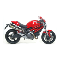
Rimontaggio pulegge albero
rinvio distribuzione
Installare sull'albero rinvio
distribuzione, lato pulegge, l'anello
elastico di arresto (25). Utilizzare per
guidarlo in sede il cappuccio di
protezione 88700.5749.
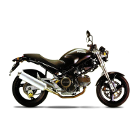
Posizionare sull'albero rinvio
distribuzione la prima linguetta (26), la
puleggia interna (29) con il mozzo
sporgente verso l'esterno e la
rondella di guida (10).
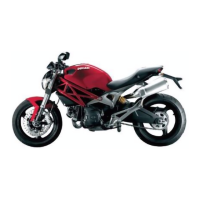
Procedere poi con il montaggio della
seconda linguetta (27), della puleggia
esterna (8) con il mozzo sporgente
verso l'interno, del distanziale esterno
(7) e della ghiera di bloccaggio (6).
Importante
Per evitare allentamenti
accidentali che causerebbero gravi
danni al motore, è necessario
utilizzare ghiere autobloccanti nuove
in corrispondenza del fissaggio di
tutte le pulegge distribuzione.
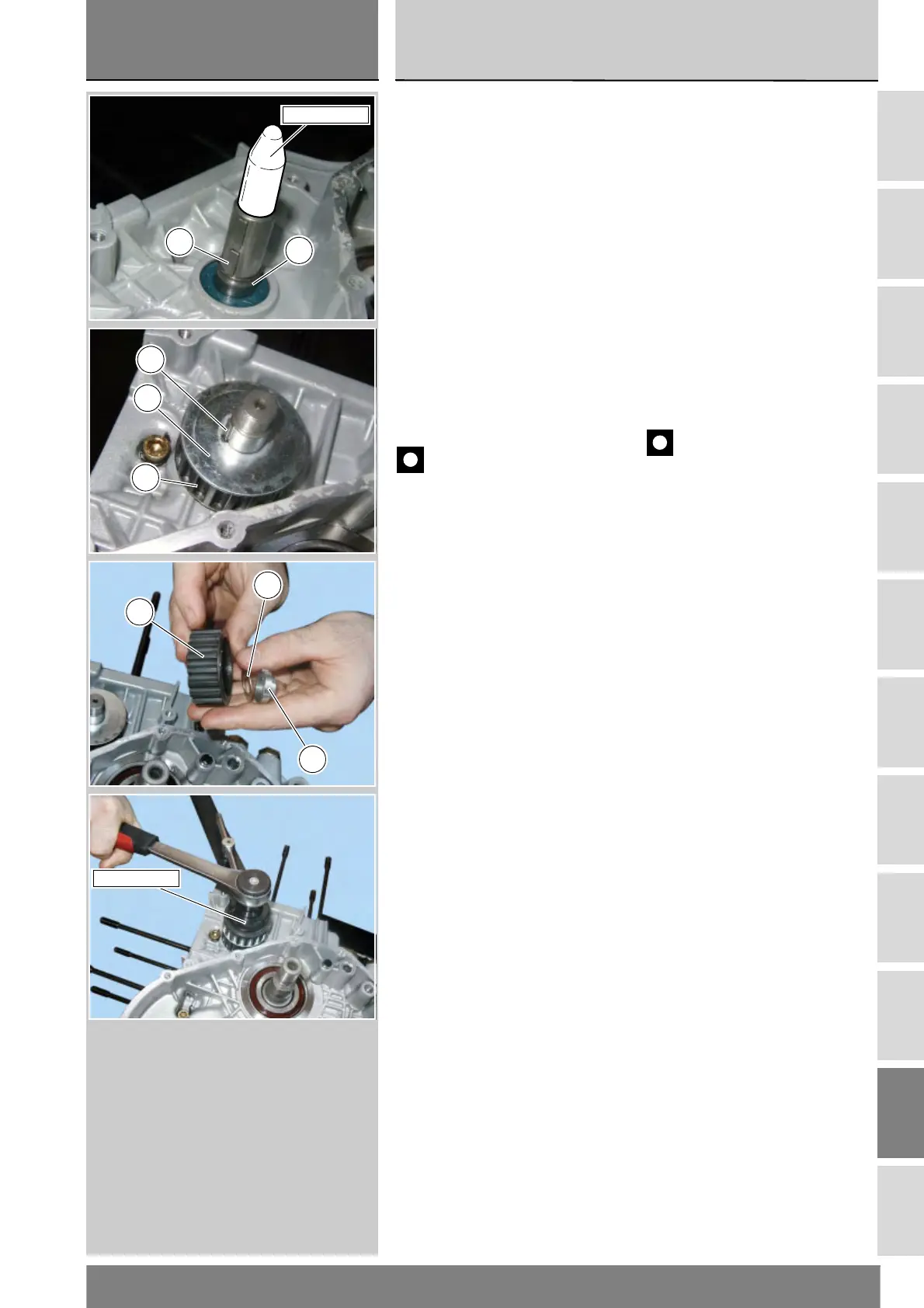
Bloccare con la chiave dell'attrezzo
88700.5644 la rotazione delle
pulegge e, utilizzando la bussola ad
esso abbinata inserita in una chiave
dinamometrica, serrare la ghiera
autobloccante alla coppia prescritta
(Sez. C 3).
Reassembling timing belt
rollers on layshaft
Working from the belt roller side, fit
snap ring (25) on the timing layshaft.
For correct snap ring positioning,
insert a protection cap part no.
88700.5749 on the end of the timing
shaft.
Fit the first key (26), the inner belt
roller (29) with the projecting hub
pointing outwards and the guide
washer (10) on the timing layshaft.
Fit the other key (27), the outer belt
roller (8) with the hub facing inwards,
the outer spacer
(7) and the locking ring nut (6).
Caution
To prevent accidental loosening
which would seriously damage the
engine, use new self-locking ring nuts
to secure all timing belt rollers.
Use the spanner of service tool part
no. 88700.5644 to lock belt roller
rotation. Fit the bush supplied with
the tool to a torque wrench and
tighten the self-locking ring nut to the
specified torque value (Sect. C 3).
25
26
88700.5749
27
10
29
8
7
6
88700.5644