A
B
C
D
E
F
G
H
L
M
N
P
Motore
Engine
sezione / section
N 7.1
109Monster 400/620 - M.Y. 2004 - edizione/edition 00
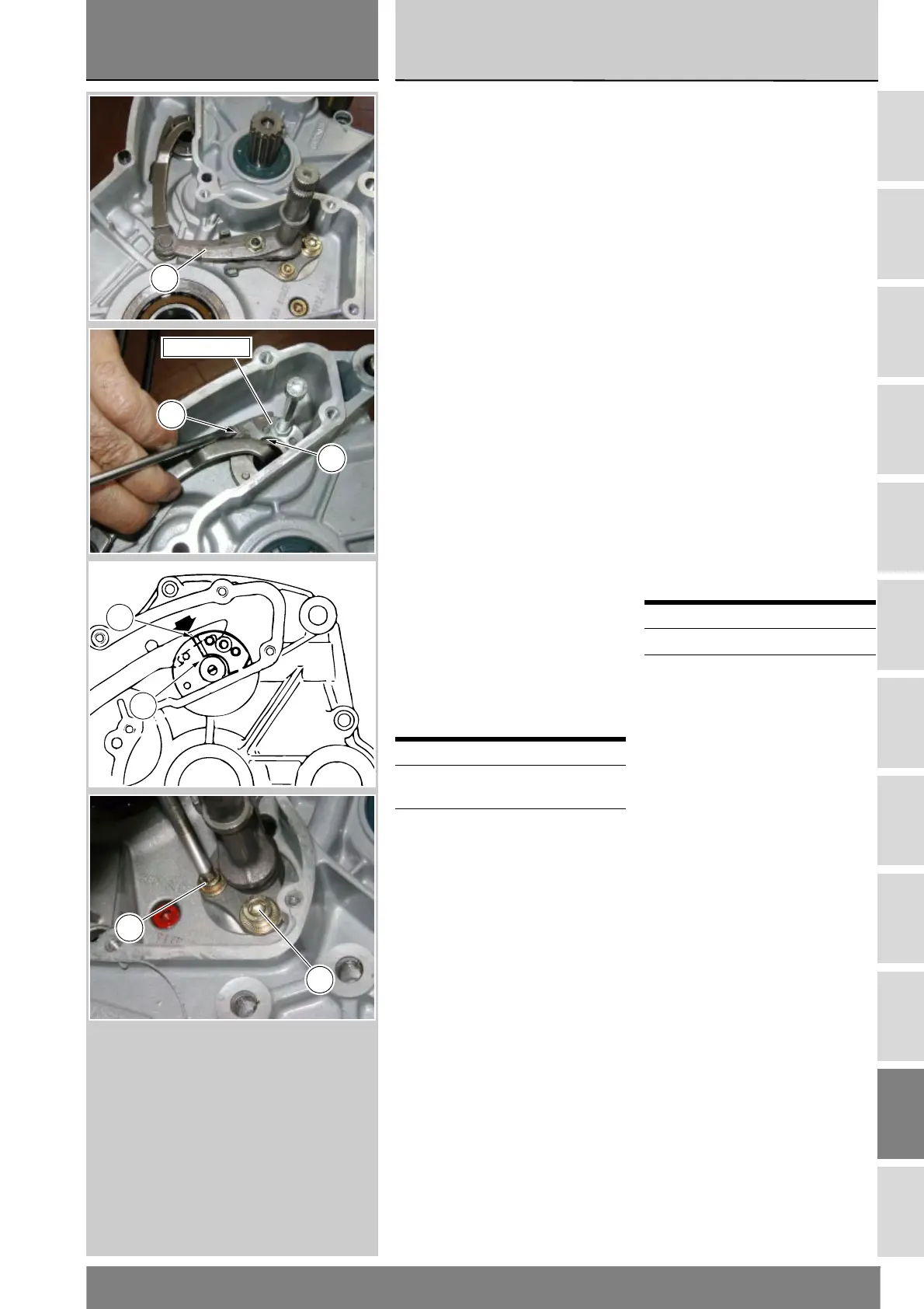
Rimontaggio leveraggio
selezione marce
Posizionare nel semicarter lato catena
il leveraggio di selezione marce (25)
completo.
Posizionare la forcella comando
tamburo del cambio centrato rispetto
ai rullini del tamburo.
Montare provvisoriamente la leva del
cambio (o una leva di servizio) e
mettere il cambio in terza marcia.
Installare il piastrino 88713.1091 nei
perni dell'albero comando forcelle
(come mostrato in figura).
Allineare la tacca (A), corrispondente
alla mezzeria dell'arpione di
spostamento albero comando
forcelle, con l'estremità del piastrino
(B).
Su questa posizione serrare le viti (18)
e (20) di fissaggio del leveraggio di
selezione marce (Sez. C 3).
Con cambio in posizione di riposo
verificare che la corsa della leva in
fase di innesto e in scalata risulti
uguale. Analoga situazione deve
verificarsi anche con marcia inserita.
Agendo sulla leva comando cambio e
contemporaneamente ruotando il
pignone provare l'inserimento di tutte
le marce in fase di innesto e in
scalata.
Rimuovere la leva cambio.
Operazioni Rif. Sez.
Rimontare la campana
frizione
N 6.3
Rimontare il gruppo
volano/alternatore e il
coperchio alternatore
N 8
Reassembling the gear
selector lever
Position the complete gear selector
lever (25) into the chain-side casing.
Position the gearbox drum selector
fork in the centre of the drum rollers.
Temporarily fit gear change lever (or a
service lever) and shift to third gear.
Fit plate part no. 88713.1091 to the
fork shaft pins (see figure).
Align the notch (A), which marks the
centreline of the fork shaft pawl, with
the end of the plate (B).
Tighten the gear selector lever
retaining screws (18) and (20)
(Sect. C 3).
With the gearbox in neutral, check
that lever travel is the same when
shifting up and down. The same
should apply when a gear is engaged.
Operate the gear change lever and
turn the sprocket at the same time to
check that all the gears engage when
shifting up and down.
Remove gear change lever.
Operations Ref.Sect.
Refit clutch housing N 6.3
Refit flywheel/
generator assembly
and generator cover
N 8
25
88713.1091
B
A
B
A
20
18
 Loading...