A
B
C
D
E
F
G
H
L
M
N
P
Motore
Engine
sezione / section
N 9.2
154 Monster 400 - 620 Aggiornamento/Update - M.Y. 2006 - edizione/edition 00
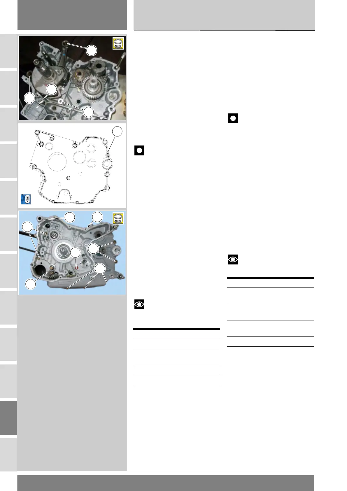
Installare l'albero motore provvisto
dei rasamenti calcolati nel cuscinetto
del semicarter lato frizione,
posizionando le bielle (B) in
corrispondenza delle rispettive sedi
dei cilindri.
Verificare che siano installate le due
boccole di centraggio (19).
Dopo averlo opportunamente
ingrassato per mantenerlo in sede,
posizionare l'anello OR (5) in
corrispondenza del canale di
comunicazione olio, tra i due
semicarter.
Importante
Accertarsi che le bielle (B) siano
correttamente posizionate nelle
rispettive sedi dei cilindri. Un
posizionamento errato porterebbe
inevitabilmente alla riapertura dei
semicarter.
Applicare il cordone uniforme e
continuo di guarnizione liquida
DUCATI (A) sulla superficie di
accoppiamento dei semi carter,
contornando tutti i fori, come
mostrato in figura.
Accoppiare i semicarter (33) e (34)
eventualmente battendo con martello
in gomma in prossimità degli alberi.
Preparare le viti di fissaggio, ed
impuntarle sul semicarter lato
alternatore (33), facendo attenzione
alle differenti lunghezze.
Note
Nel rimontaggio applicare
grasso prescritto nella vite forata (28)
di unione carter.
Avvitare fino in battuta in modo
progressivo le viti di unione, partendo
da quelle di diametro maggiore (M8).
Rif. Q.tà Descrizione
25 6 viti M8x75 mm
28 1 vite forata M8x75
mm
26 5 viti M6x35 mm
27 1 viti M6x75 mm
Fit the shimmed crankshaft into the
clutch-side casing. Position the
connecting rods (B) at their housings
into cylinders.
Make sure that the two centring
bushes (19) are fitted.
Thoroughly grease the O-ring (5) and
place it close to the oil duct
connecting the two casings.
Caution
Make sure that the connecting
rods (B) are correctly positioned in the
cylinders. Incorrect positioning will
inevitably lead to reopening of the
casing.
Apply a uniform bead of Ducati liquid
gasket (A) on the mating surface of
the casing, avoiding the holes as
shown in the figure.
Match the casings (33) and (34). Tap
the area around the shafts with a
plastic hammer, if necessary.
Start the jointing screws into their
holes on the generator-side casing
(33). The screws are not all the same
length, be sure to position them
correctly.
Note
Apply recommended grease
when refitting drilled screw (28).
Progressively tighten the jointing
screws all the way in. Begin with the
larger diameter (M8) screws.
Ref. Q.ty Description
25 6 M8x75 mm
screws
28 1 M8x75 drilled
screw
26 5 M6x35 mm
screws
27 1 M6x75 screw
5
B
B
34
B
A
25
25
26
27
28
26
33
B
 Loading...