A
B
C
D
E
F
G
H
L
M
N
P
Impianto elettrico
Electric system
sezione / section
P 1
5Monster 400 - 620 Aggiornamento/Update - M.Y. 2006 - edizione/edition 00
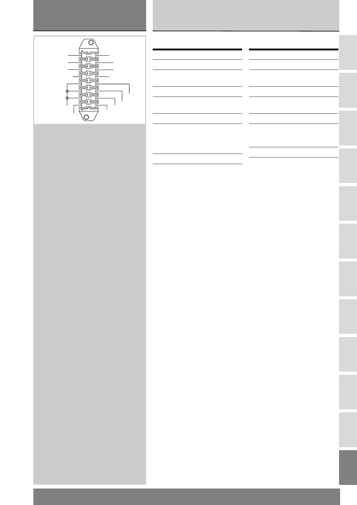
Legenda scatola fusibili
Disposizione dei cablaggi
sul motociclo
Tutti i percorsi dei cablaggi
dell’impianto elettrico sono stati
ottimizzati per avere il minimo
ingombro.
Ogni passaggio è stato studiato per
non interferire durante l’utilizzo della
moto con organi che potrebbero
danneggiarli o procurare anomalie di
funzionamento. Le tavole che
riportiamo di seguito evidenziano i
punti di origine (punti “0”) per il
riposizionamento corretto dei cavi e i
punti di posizionamento delle
fascette stringitubo.
In ogni figura sono indicati i rimandi
alle tavole nelle quali il riparatore potrà
seguire il proseguimento del cavo
interessato oppure l’utilizzatore a cui
va collegato.
Pos. Utilizzatore
Val.
1-9 Generale 30 A
2-10 Pompa benzina,
iniettori, bobine
20 A
3-11 Key sense 10 A
4-12 Alimentazione
centralina
3 A
5-13 Passing 7,5 A
6-14 Luci posizione, NQS
(cruscotto), luci
abbaglianti e
anabbaglianti
15 A
7-15 Stop, claxon 10 A
8-16 Stampella laterale 3 A
Legend of fuse box
Arrangement of wiring on
frame
Routing of wiring has been optimized
to ensure the minimum obstruction.
Each section is designed to prevent
interference with parts that might
damage wires or cause operating fail-
ures when riding. The diagrams on
the following pages show the origins
(“0” points) for cables proper re-rout-
ing and cable ties locations.
Each figure includes references to the
diagrams showing the cable routing
or the item it will have to be connect-
ed to.
Pos. Description
Val.
1-9 Main fuse 30 A
2-10 Fuel pump, injectors,
coils
20 A
3-11 Key sense 10 A
4-12 Control unit power
supply
3 A
5-13 Passing 7.5 A
6-14 Parking lights, NQS
(instrument panel),
high and low beam
15 A
7-15 Stop light, horn 10 A
8-16 Side stand 3 A
Bn
R/B
Y/B
V
R
R/Y
R/W
R/Bk
R/Bk
Bk
R
Y/B
Bk/Gr
R/G
1
2
3
4
5
6
7
8
9
10
11
12
13
14
15
16