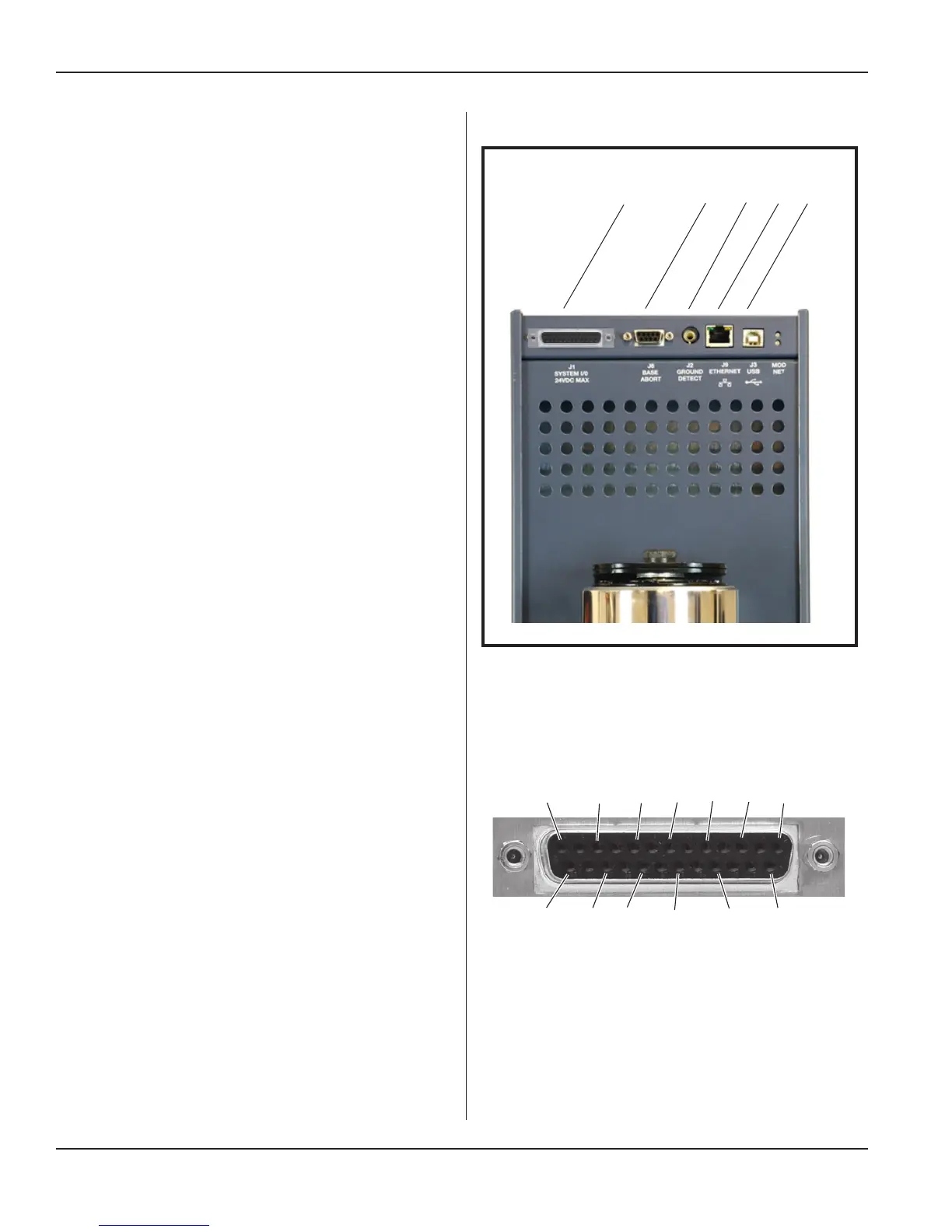
System I/O Panel
The standard system I/O panel is described here.
See Figure 3-4.
System I/O Connector (J1)
The SYSTEM INPUTS/OUTPUTS connector mounted on
the system I/O panel (See Figure 3-5.) includes connec-
tions for all of the basic system control input and output
signals that will typically be associated with an automated
control system.
The cable attached to this connector includes all of the
available system control signals, which will be controlled
by an output card or output port on the automation con-
troller.
The user can determine which signals to use for each
welding application, but with an automatic control system
there must be at least one connection to this connector in
order to activate the ultrasound output.
Most of the digital output status signals on this connector,
are isolated PHOTOMOS relays (signals are not refer-
enced to generator chassis ground). When an output is
active, these relays are closed (the output is connected to
Isolated Common). This conguration supports PNP and
NPN automation inputs, depending on how the common
is terminated. The maximum current is 400mA sourced
from a 24VDC supply.
All of the input signals on this connector are electrically
isolated (signals are NOT referenced to chassis ground)
and can be driven from an automation controller output
that is either sinking (NPN) or sourcing (PNP), depending
upon how the isolated common connection is terminated.
Signals are activated when the voltage difference between
the signal and the isolated common pin is 24V.
All inputs sink or source 10mA of current from a 24VDC
power supply.
Note that a simple switch closure (relay contact) connect-
ed to a control input can not activate the input without
adding an external power supply to power the input. Add-
ing jumper connections to pins available on the System
I/O connector, can congure switch closure inputs to op-
erate referenced to press chassis ground (non-isolated),
without adding a separate power supply, if desired.
Refer to Application Note AN515 (i220 Integrated Press
- Automation Interface) at http://www.dukane.com/us/
DL_ApplData.asp for wiring diagrams of example ap-
plications.
Figure 3-4 System I/O Panel (Standard Panel Shown)
Continued from Previous Page
Continued
System I/O Panel Connectors (5)
J1
S
yst
e
m
I
/
O
J
6
B
a
s
e
A
b
o
r
t
J
2
G
r
o
u
nd
De
t
e
c
t
J
9
E
t
h
e
r
N
e
t
J
3
U
S
B
Figure 3–5 DB-25F, Press Input/Output Cable
Connector (J1)
13 11 9 7 5 3 1
25 23 21 19 17 15
Page 20
iQ Series Ultrasonic Integrated Press System i 220 User’s Manual
Dukane Manual Part No. 403-594-02
 Loading...