NOTE
The actual amount of force applied to
the part depends on the following four
factors:
• The setting of the regulator(s)
• The area of the air cylinder
• The mass of the horn used
• The surface area of the horn
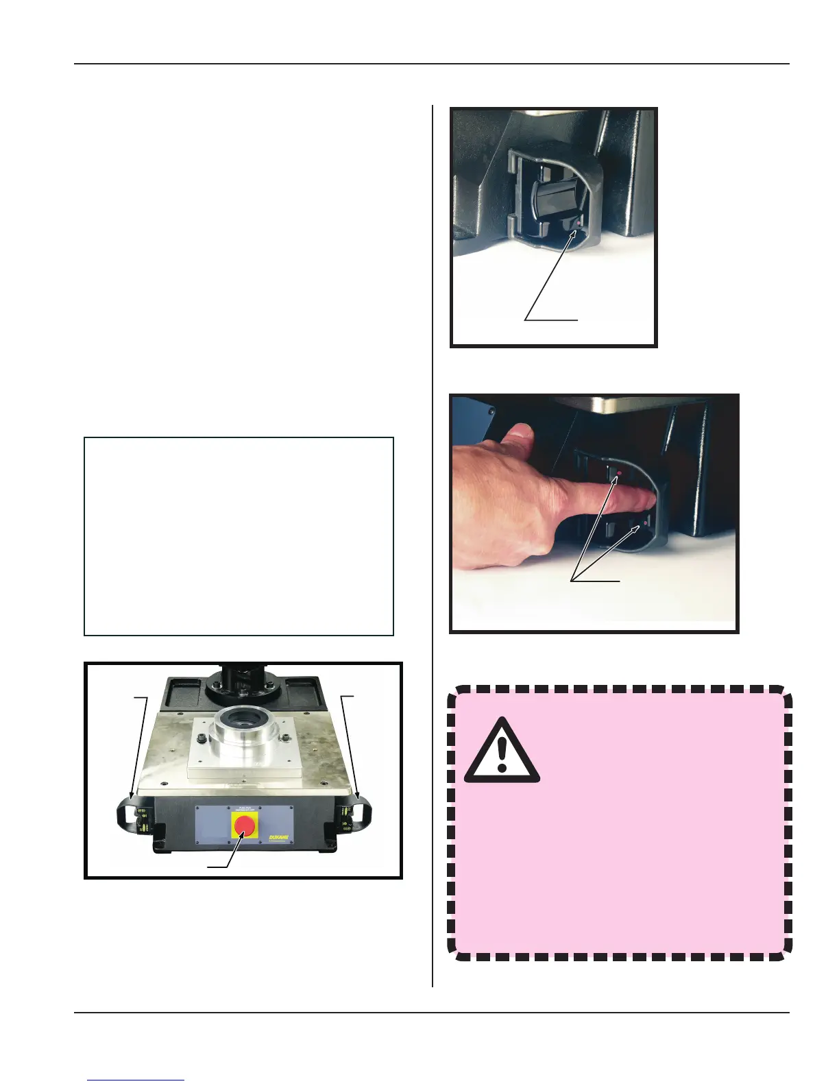
Press Ergonomic Base
The ergonomic base, shown in Figure 4-13, consists
of a base plate, cycle activation switches (black nger
switches), abort switch (red palm switch). At the back of
the base is a cable connector for an interface between the
i220 thruster and the base front panel.
Base Plate
The machined base plate is bolted to the top of the ergo-
nomic base. It has drilled and tapped holes that line up
with leveling screws in the xtures to allow easy xture
leveling for alignment with the horn. For details on the
alignment and leveling of the base plate, see Section 7:
Acoustic Stack/Fixture Setup.
Right
Operate
Switch
Lower Fixture
Lower Fixture
E–Stop Switch
Left
Operate
Switch
Figure 4-13 Ergonomic Base Controls
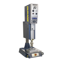
Dimly Lit
Red LED
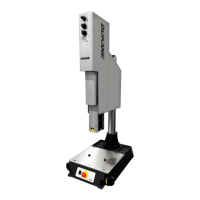
Figure 4-15 Right Switch in Operate Mode, Both
LEDs Brightly Lit
Figure 4-14 Right Operate Switch in Standby
Mode, One LED Dimly Lit
Any modications to the Ac-
tivation Switch (also known
as the Operate Switch) circuit
must comply with all OSHA
and ANSI requirements. Compliance
with all local building and electrical
codes is also required.
Dukane Corporation does not assume
any responsibility or liability for circuit-
ry modications made by the customer
or by any third party manufacturer.
WARNING
Page 45
Dukane Manual Part No. 403-594-02
Section 4 - Controls
 Loading...