87 … 96
86 … 96
Printed in Germany • Edition 04.18 • Nr. 271 958
Flame detector
Operation requirements of separate
ame detectors on the MPA 41xx PF:
The ame detectors must be tested
and approved for monitoring gas burn-
ers.
The reaction times must be ob-
served!
Total reaction time = reaction time MPA
+ reaction time ame detector.
A proof about the compliance with the
requirements of EN 298 is required.
The reaction time after a ame lift-o of
an external ame detector may not be
longer than the start-gas safety time.
When connected to FLW1, the ioni-
sation behaviour of a ame must be
simulated (rectier eect). The follow-
ing values are active on the ionisation
input and output of the MPA:
230 VAC +10 % -15 %.
The internal resistance of the MPA is
approx 1 MΩ. For safety reasons, the
ame sensor must work properly also
with an internal resistance of 360 kΩ.
Under these conditions, the simulation
circuit in the ame detector must reach
at least a direct current 3 µA.
If an alternating current with a DC com-
ponent is simulated, the DC compo-
nent should not drop below 25 %.
The current can be derived to N, PE or
returned to N on the MPA.
The EMC regulations must be ob-
served (EN 298). The entire system
must not produce inadmissible emis-
sions.
MPA 41xx PF is not galvanically iso-
lated.
MPA 41xx PF and the ame detector
must be connected according to the
correct phase.
Attention
DUNGS cannot be held liable if the
ame detector and the automatic burn-
er control system do not work orderly
together. Especially if the electromag-
netic behaviour is not according to the
regulations or if the time-dependent
behaviour is not correct.
The quality of the ame signal is
displayed for ame detector 1 as a
number between 0 and 58.
Evaluation of the ame signal is only
possible with ionisation ame monitor-
ing and monitoring with UV41 (HE).
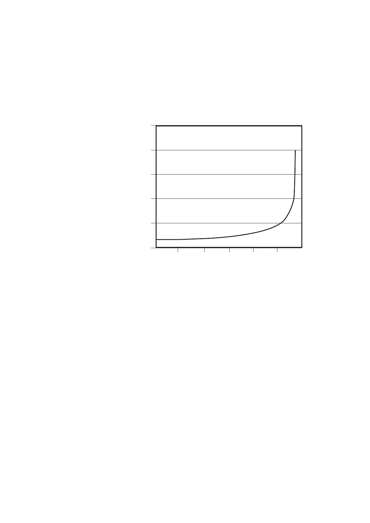
25
ION / μA
20
15
10
5
0
10
20
30 40 50 60
ION vs. digits MPA41
digits
 Loading...