33
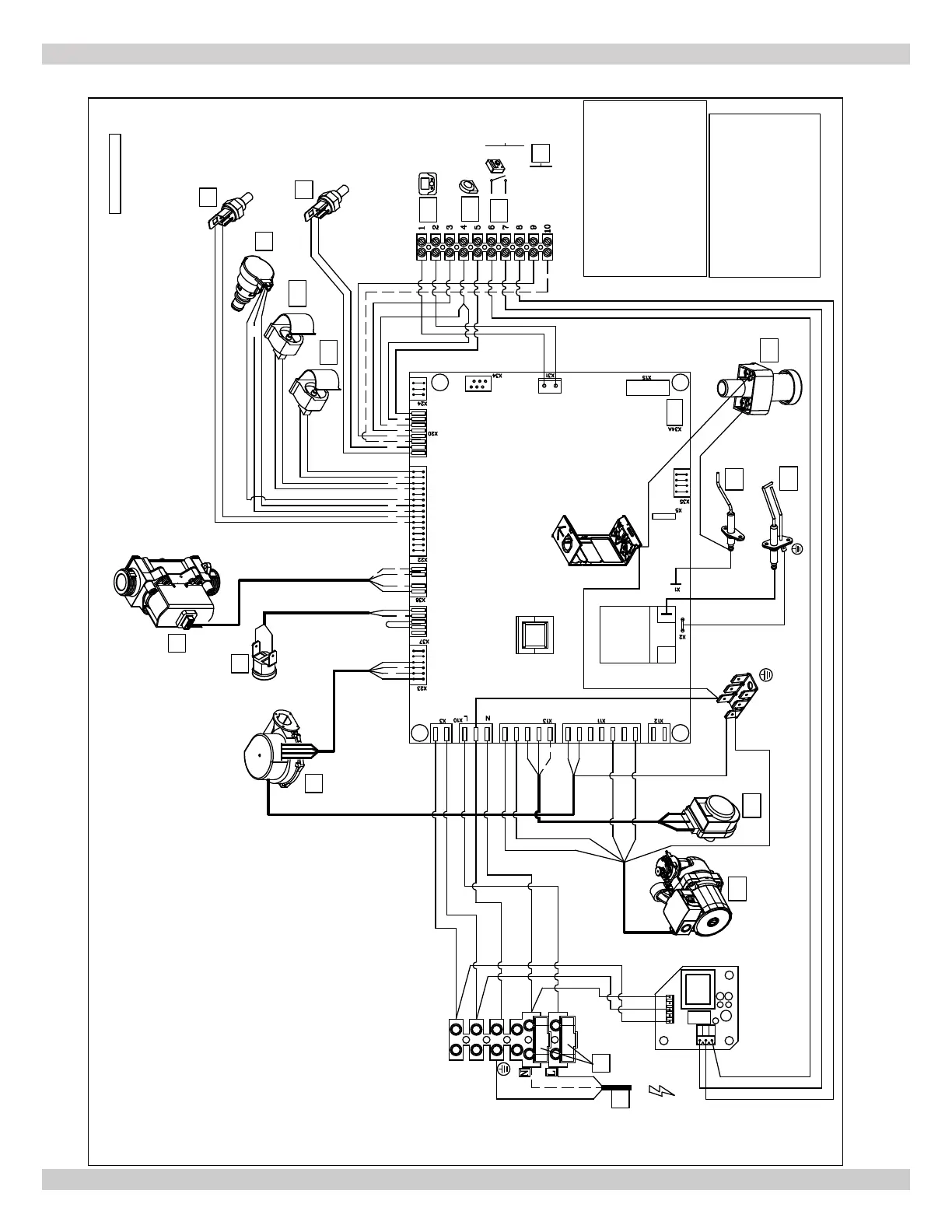
100 - HEAT ONLY WIRING DIAGRAM
Bl= Blue - Bleu
Br= Brown - Brun
Bk= Black - Noir
R= Red - Rouge
G/Y= Green / Yellow - Vert / Jaune
W= White - Blanc
G= Green - Vert
Gr= Grey - Gris
lB= Light Blue - Celeste
WIRING DIAGRAM
If any of the original wire as supplied
with the appliance must be replaced, it
must be replaced with wire having
same specifications.
SCHEMA DE CABLAGE
Si un câble d'origine, tel qu'il est fourni
avec l'appareil, doit être changé,il doit
être remplacé par un câble qui
possède les mêmes caractéristiques.
LEGEND - LEGENDE:
1-Fuses 3,15 A - Fusibles 3,15 A
2-Supply 120V - 60Hz - Alimentation
4-Fan - Ventilator
5-Safety Thermostat - Thermostat de Sécurité
6-Gas valve - Vanne a gaz
7-Exchanger sensor - Sonde échangeur
8-Water Pressure Switch - Pressostat Eau
9-NTC return Sensor - Sonde NTC retour
10-NTC flow sensor - Sonde NTC départ
11-Remote User Interface or Open Therm
12-Prov. for Outside Sensor - Pred. Sonde Extérieure
13-Link 24V - Joint 24V
14-Flame Sensing Electrode - Electrode présence veilleuse
15-Ignition Electrode - Electrode d'allumage
16-Three Way Valve - Soupape Trois Voies
17-Pump - Pompe
18-Flue Safety Thermostat - Thermostat Fumées
19-Link 0 - 10V - Joint 0 - 10V
20-Condensate sensor - Capteur de condensation
M1 - Main Power Terminal Board - Bornier d'alimentation
M2 - AccessoriesTerminal Board - Bornier pour accessoires
M1
1
2
4
6
5
7
8
9
10
14
15
16
17
12
11
18
R
G/Y
G/Y
G/Y
G/Y
G/Y
G/Y
G/Y
G/Y
G/Y
G/Y
G/Y
Bk
W
G
Bk
R
Bk
R
Bk
BkBk
Bk
Bk
Bk
Bk
Br
Br
Br
Br
G
G
R
R
W
R
G
Bl
Bl
Bl
Bl
BkBr
Bl
Bl
Bl
G
W
R
R
Br
Bk
Bl G
Bl
Bl
Bl
Bl
R
R
G
G
R
Bk
G
Bl
Bl
Bl
Br
Br
Br
Gr
G
W
Br
Gr
Bl
Bk
R
Bl
4 5 6
3 2
1
Bk
R
13
24V
120V
M2
R
Bk
lB
lB
24 V Max 10 mA
Br
Bk
W
Bk
R
- IN
+ 0 - 10 V
19
20
G/Y
240013362 REV A
MODEL 100 - Heat Only
PN 240011430 REV. O [07/01/2021]