33
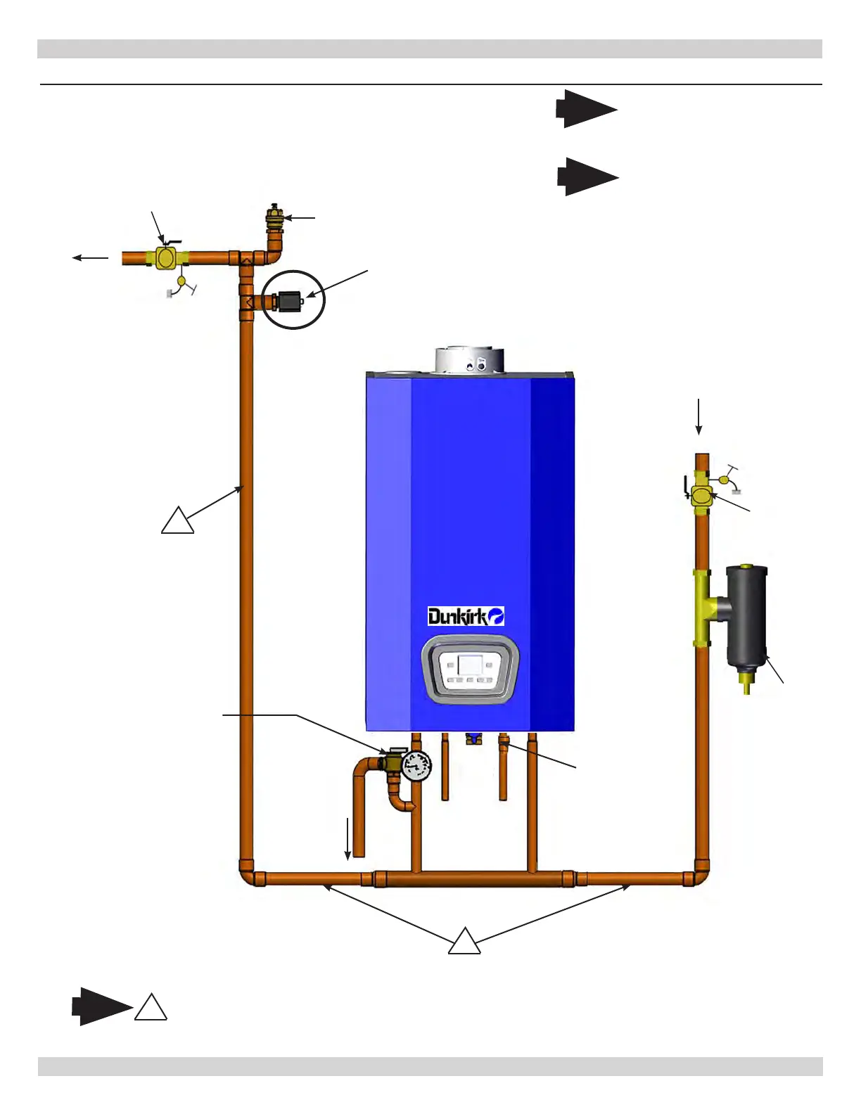
FIGURE 6-3 - Piping Diagram - LWCO Location
6 - HYDRONIC PIPING
(See Figure 6-5 for detail)
Air Vent
Supply
Gas
Boiler
Safety Relief
Valve
Position LWCO Above
Top of Boiler
1
DO NOT PLACE ISOLATION VALVE
BEFORE TEE OR LWCO.
Note
1
*To Drain
* Check Local Codes for
Maximum Distance to
Floor.
Arrange piping to prevent
water dripping onto boiler.
1
Return
5 gpm Limiter
Factory Installed
205 Only
Purge Valve
Magnetic
Dirt
Separator
Purge Valve
240013360
REV A [07/01/2021]
Note
Illustrations are meant to
show system piping concept
only. Installer is responsible
for all equipment and detailing
required by authority having
jurisdiction.
Note