25
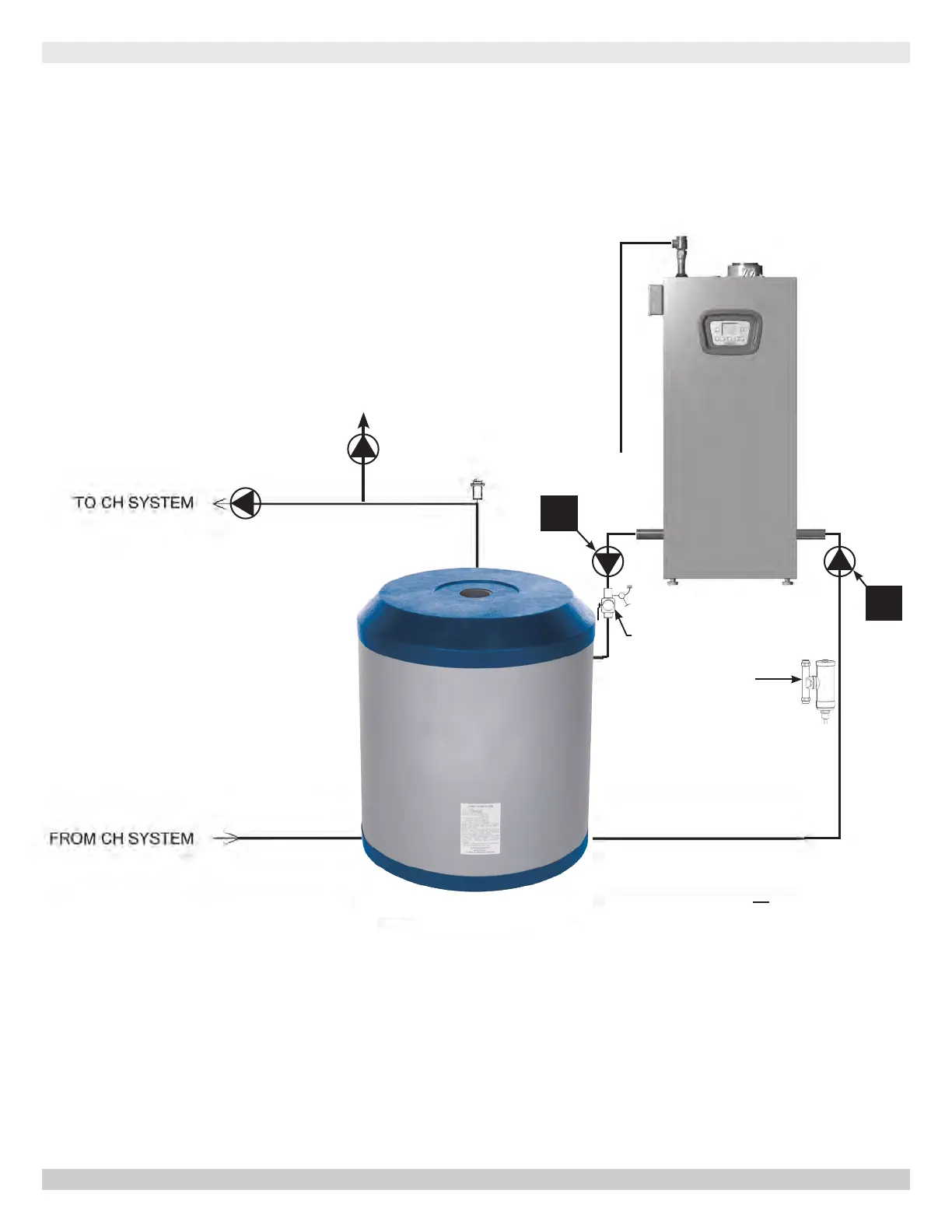
EXTERNAL BUFFER TANK - PIPING DIAGRAM
H2O Stainless
Steel Buffer
Tank
PURGE
VALVE
CH System Pump
Optional Indirect Tank
ZONE PUMPS OR ZONE VALVES
MAGNETIC
DIRT
SEPARATOR
1
2
NOTE : Acceptable primary pump
locations: Either 1 or 2.
For pump wiring see diagrams on
pages 26-29.
Buffer Tank On Central Heat Circuit With Primary Pump and Supplied Manifold
PN 240012875 REV. B [07/01/2021]