10
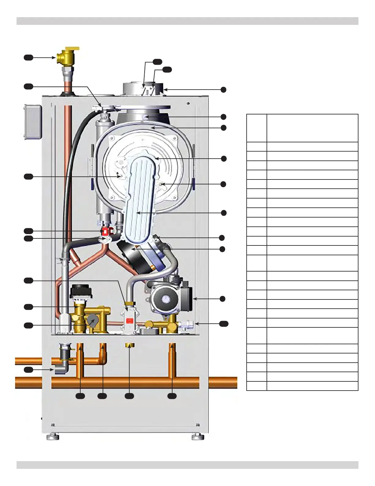
3 - COMPONENT LISTING
Illustrations are a depiction of the boiler for general location of parts and may vary depending on model.
ITEM
NO.
Dunkirk
DCBF-125
1 Coaxial Connector
2 Flue Sensor
3 Heat Exchanger
4 Burner (not shown)
5 Flame Detection Electrode
6 Air/Gas Blend Manifold
7
Venturi
8 Fan
9
Pump with Air Separator
10 Boiler Drain Tap
11 Heating Return
12 Gas Inlet
13
Optional Indirect Tank
Connection
14 Heating Supply Connection
15 Condensate Connection
16
17 3-Way Valve with Motor
18 Gas Valve
19 Water Safety Thermostat
20
NTC Heating sensor (Flow/Return)
QTY 2, (1 Shown for clarity)
21 Ignition Electrode
22 Pressure Switch
23 Pressure Relief Valve
24 Exhaust Test Port
25 Intake Test Port
9
2
4
1
3
6
5
7
8
10
13
22
24
25
20
19
21
111214
15
16
17
18
23
240013375 REV A, [07/01/2021]
DUNKIRK DCBF-125