20
GENERAL INSTRUCTIONS
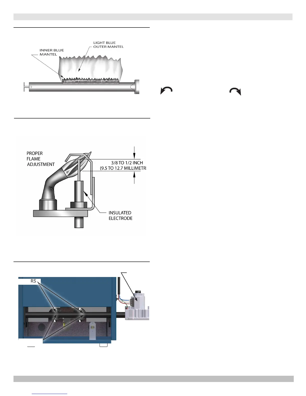
Figure 18 - Gas Burner Flame
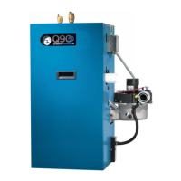
Figure 19 - Gas Burner Pilot
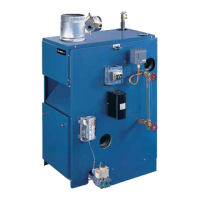
Figure 20 - Combustion Chamber
BURNERS
ORIFICES
GAS VALVE
• Make visual inspection of main burner and pilot ames
at start of heating season and again in mid-season. Main
burner ame should have well dened inner blue mantel
with lighter blue outer mantel. Check burner throats and
burner orices for lint or dust obstruction. Figure 17 and
18
.
• Pilot ame should envelop ⅜ to ½ inch of tip of ignition/
sensing electrode. See
Figure 19
.
• To adjust pilot ame, remove pilot adjustment cover
screw and turn inner adjustment screw counterclockwise
to increase or clockwise to decrease pilot
ame. Be sure to replace cover screw after adjustment to
prevent possible gas leakage. See Figure 16, Page 19.
• Check burners and pilot for signs of corrosion, rust or
scale buildup.
• Area around boiler must be kept clear and free of
combustible materials, gasoline and other ammable
vapors and liquids.
• Free ow of combustion and ventilating air to boiler and
boiler room must not be restricted or blocked.
• Inspect eld sourced low water cutoffs annually, or
as recommended by low water cutoff manufacturer.
Flush oat type low water cutoffs per manufacturer's
instructions.
• Employ a qualied service agency to make annual
inspection of boiler and heating system. They are
experienced in making the inspections outlined above,
and, in event repairs or corrections are necessary,
trained technicians make the proper changes for safe
operation of the boiler.
P/N 240009041, Rev. C [04/30/2017]