19
Thermostat actuates on call for heat, completing
circuit to control. Completed circuit to control will
rst activate circulator and damper which will close
end switch inside damper. Completes circuit to
ignition system, ignition takes place.
In event boiler water temperature exceeds high
limit setting on boiler mounted high limit control,
power is interrupted between control system and
ignition system. Power remains off until boiler
water temperature drops below high limit setting.
Circulator continues to operate under this condition
until thermostat is satised.
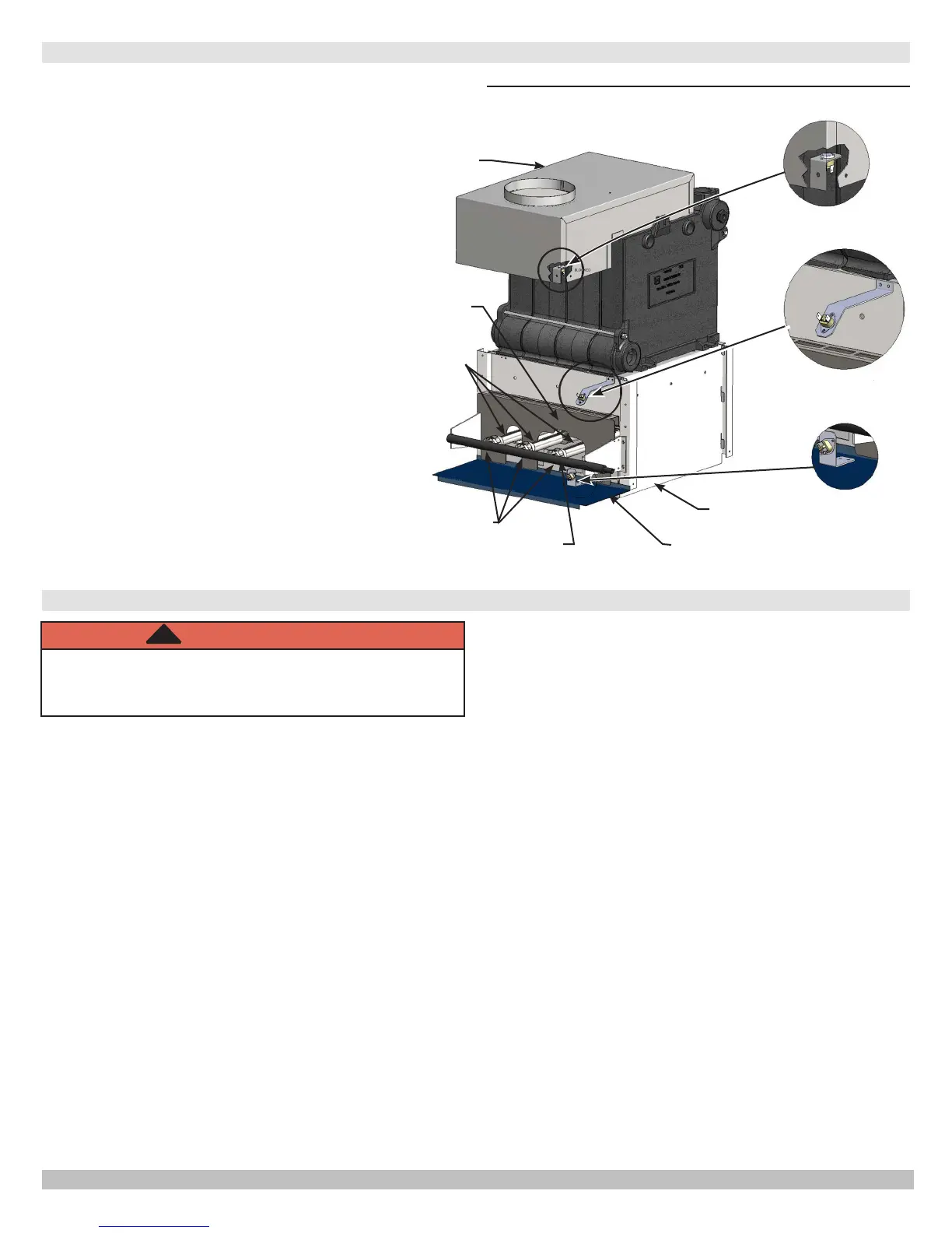
In event ow of combustion products through boiler
venting system becomes blocked, blocked vent
safety switch shuts main burner gas off. Similarly, if
boiler ue-way becomes blocked, ame rollout safety
switch shuts main burner gas off. Figure 17. If
either of these conditions occur, DO NOT ATTEMPT
TO PLACE BOILER BACK INTO OPERATION.
CONTACT CERTIFIED SERVICE AGENCY.
Before seasonal start-up, have a certied service agency
check boiler for soot and scale in ues, clean burners and
check gas input rate to maintain high operating efciency.
Verify proper operation after servicing
Service agency will verify system is lled with water to
minimum pressure and open air vents, if used, to expel any
air accumulated in the system. Check entire piping system
and, if any leaks appear, have them repaired.
Circulators need to be checked and maintained. Refer
to circulator manufacturer's instructions
.
Inspect venting system at the start of each heating
season. Check vent pipe from boiler to chimney for signs of
deterioration by rust or sagging joints. Repair if necessary.
Remove vent pipe at base of chimney or ue and using a
mirror, check vent for obstruction and verify vent is in good
working order.
Boiler ue gas passageways may be inspected by a
light and mirror. Remove burner door. See
Figure 17
.
Place trouble lamp in ue collector through draft relief
opening. With mirror positioned above burners, ue gas
passageways can be checked for soot or scale.
This procedure should be followed to clean ue gas
passageways:
1.
Remove burners from combustion chamber by raising
burners up from manifold orices and pulling toward
front of boiler. See
Figure 17
.
2.
Disconnect vent pipe from draft hood.
3.
Remove top jacket panel.
4.
Remove combination ue collector and draft hood from
boiler castings by loosening nuts on hold down bolts
located on each side of collector. See
Figure 17.
5.
Place sheet of heavy paper or similar material over
bottom of base and brush down ue passageways. Soot
and scale will collect on paper and is easily removed
with the paper.
6.
With paper still in place in base, clean top of boiler
castings of boiler putty or silicone used to seal between
castings and ue collector. Verify chips are not lodged
in ue passageways.
When cleaning process is complete, restore boiler
components to their original position. Use IS-808 GE
silicone (available from distributor) to seal around ue
collector and boiler castings.
SEQUENCE OF OPERATION
GENERAL INSTRUCTIONS
Blocked Vent
Safety Switch
Rollout Switch
4 Section Boiler
Rollout Switch
2,3,5
Section Boiler
Integral Draft
Hood
Base
Burner
Door
Burners
Orices
Jacket Base
Panel
Manifold
Figure 17 - Blocked Vent Safety Switch, Roll-out
Safety Switch
WARNING
Label all wires prior to disconnection when servicing
controls. Wiring errors could cause improper and
dangerous operation.
!
P/N 240009041, Rev. C [04/30/2017]