Observe the commercial gas equipment installation criteria and operation criteria.
21
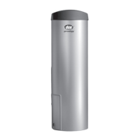
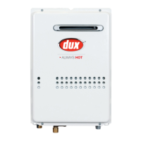
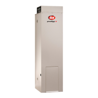
Installation Manual
See Dux for individual flueing components part numbers.
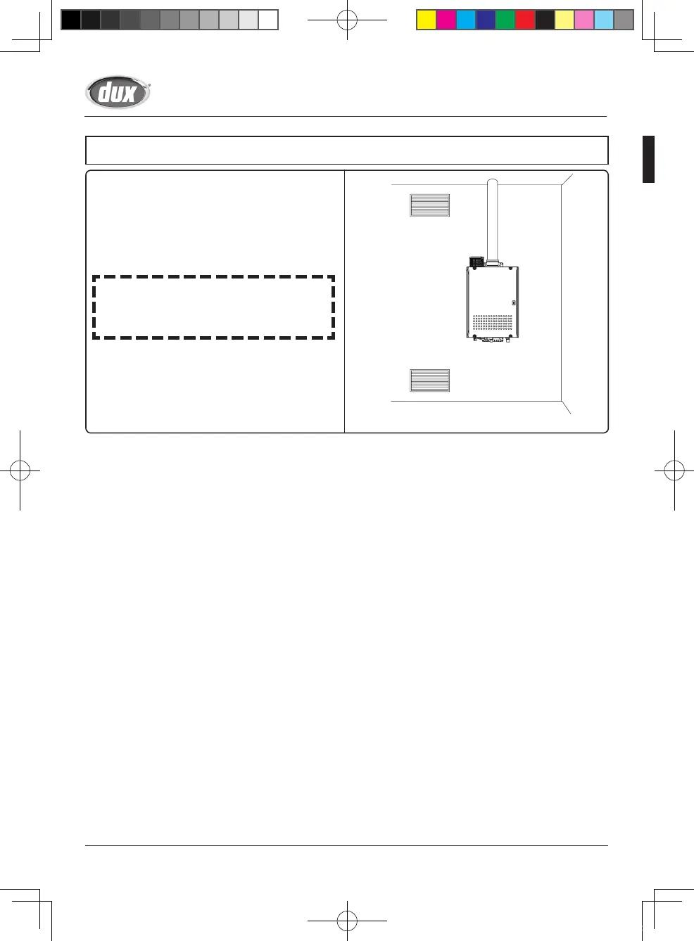
Horizontal Flue Termination
Example of flue installation instruction
General
• Store material inside.
• Check the components on possible damages.
• Use only flue components Dux part numbers listed under optional accessories.
• Install after national regulation
Fill out chimney label (when supplied) and place it near boiler adaptor.
Cleaning
Outside can be cleaned with a wet towel or with some detergent
Install products according to national regulations. Printing errors or technical alterations reserved.
In case of doubts ask sales department for advice.
1. Check the flue terminal for
possible damage.
2.
Determine the proposed
location of the flue terminal.
4. Determine the thickness of the wall and cut if necessary the
wall terminal to the corresponding length.
Remove the burs. Attention: the length is correct if the outer
wall plate or rosette are flush with the outside wall.
3. Drill a hole through the wall of a maximum of 10 mm wider than the
air supply pipe for the flue terminal.
Horizontal flue terminals with flexible exterior gaskets can be
installed inside out, in which case the drilled hole must be 25 mm
wider than the diameter of the air supply pipe. Take due care to
protect the appliance from dust and grit during drilling.
5. Insert the flue terminal into the
drilled hole.
The air supply pipe for the flue
terminal must either be installed
level or tilted slightly downwards
to the outside (max. 10 mm per
meter). To prevent rainwater from
penetrating the system, ensure
that the flue terminal is never
installed up side down.
Installation Sequence