SDI-01
Feb ‘15
- 6 -
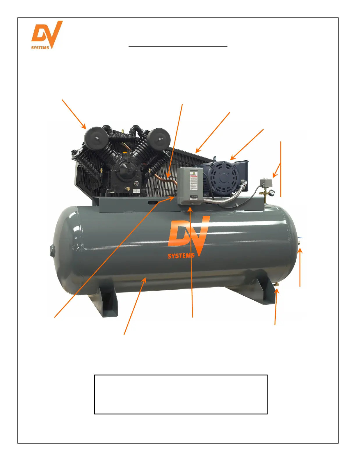
Compressor Terminology
Please refer to the picture below, as it identifies the major components of a typical Piston Air Compressor Unit
and their function. A horizontal Unit is shown.
A Switch which starts and
stops the Unit at a
predetermined minimum
and maximum pressure.
Pressure Gauge
Reflects Tank pressure.
Safety Valve
Compresses the air.
Protects personnel from the
moving parts of the Flywheel,
Pulley, and Belts.
Allows the compressed air
to cool as it transfers from
the Pump to the Tank.
Electric Motor
Installed between the
Aftercooler and the Tank, and
allows the compressed air to
enter the Tank, but prevents it
from flowing back out.
Stores the compressed air.
An electrical device which
receives a signal from the
Pressure Switch and
allows power to flow to the
Motor.
Allows the Customer to
drain moisture from the
Tank.
Discharge/outlet from
Tank.
Pump Components
Please refer to the Compressor Pump information provided in
this manual to identify the part numbers, location, and
quantities for your particular Pump model.