EasyManua.ls Logo

DynaGen ES52 - 2. Wiring Installation Guidelines; 2.1 Wire Sizing

DynaGen ES52
25 pages
Print Icon
To Next Page IconTo Next Page
To Previous Page IconTo Previous Page
Loading...
Operating & Installation Manual for the ES52 Engine Controller
7
2. Wiring Installation Guidelines
Danger: The controller does not generate a warning prior to Automatic Engine
start. Do not work on the Engine while power is applied to the unit. It is highly
recommended that warning signs be placed on Engine equipment indicating the
above.
Following these instructions will help avoid common installation problems during wiring and
setup.
Battery must be disconnected before any wiring connections are made.
Wire length from the engine to the controller should not exceed 6 meters (20 feet).
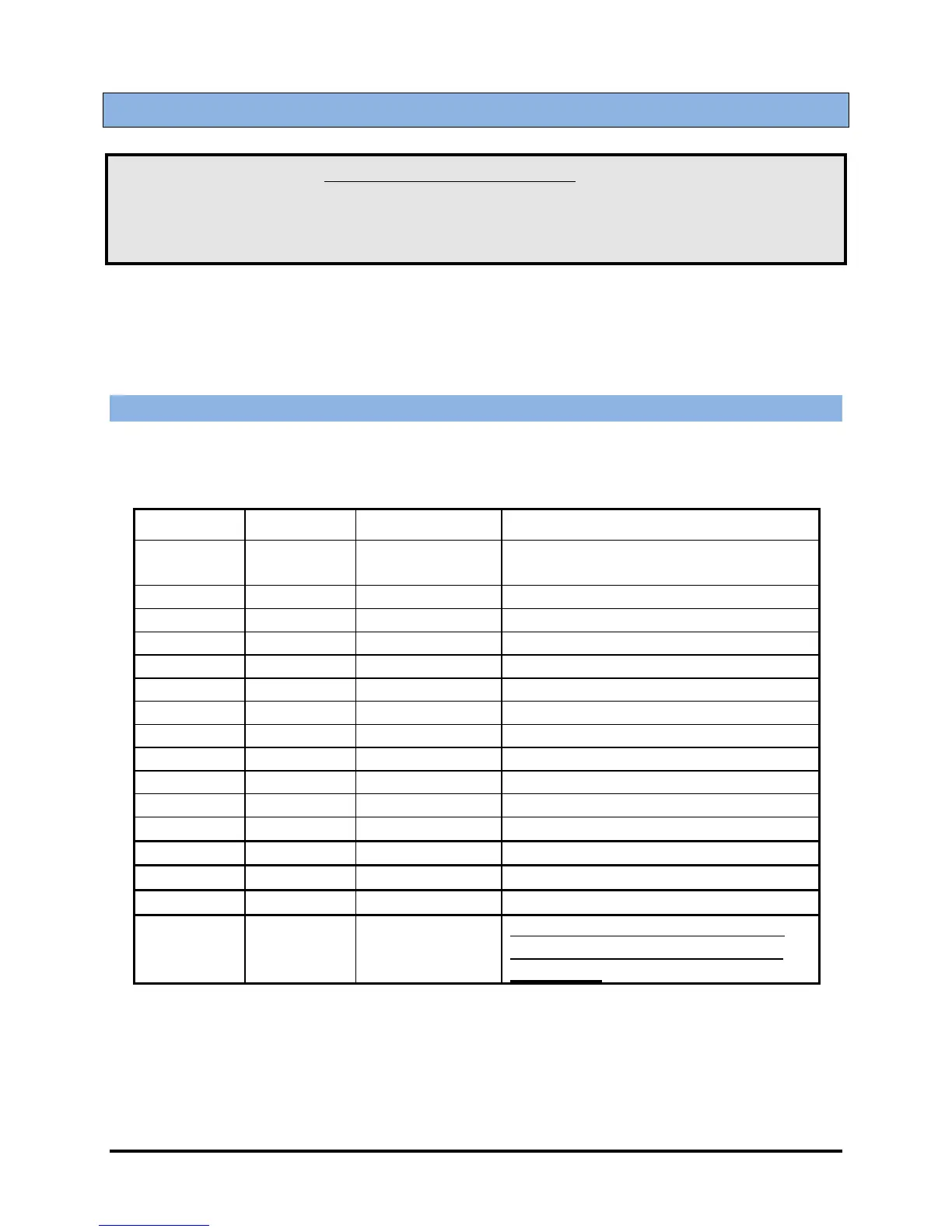
2.1 Wire Sizing
Wiring size and type should be as specified below. Use stranded wire, since solid wire has a
tendency to crack, break and loosen over time.
Terminal
Wire Size
Current max.
Function
CON 1
18
100mA
Speed signal connection via on board
connector
1
18
100mA
LED Test Switch
2
18
7mA
Oil Pressure Switch
3
18
7mA
High Temperature Switch
4
18
7mA
Auxiliary Input Switch
5
14
10 A
Starter Solenoid/Pilot Relay
6
12
20 A
Battery negative (-)
7
12
20 A
Auto Switch
8
12
20 A
RSC1 (remote start contact connection)
9
12
20 A
RSC2 (remote start contact connection)
10
12
20 A
Start/Stop Connection
11
14
10 A
Fuel Solenoid/Pilot Relay
12
18
300mA
Timer Output
13 to 18
18
300mA
Annunciation Outputs
19
18
300mA
Warmup Output
20
18
300mA
Annunciator Common Ground Only
(DO NOT use this as main ground
connection)

Related product manuals