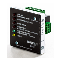
Operating & Installation Manual for the ES52 Engine Controller
2.3 Terminal Descriptions
Speed signal input for crank disconnect, engine run, and over-speed sensing. Generator
output, magnetic pickup (MPU) sensor, or alternator output can be used.
- Use at least twisted pair wiring for this connection.
- Polarity does not matter.
- Use two female 0.250” inch insulated female quick connects for the connection.
For MPU Sensor:
- One side of the MPU must both be grounded and connected to the controller
otherwise erratic behavior can result.
- Use a shielded MPU with a shielded cable grounded at one end only for best
reliability.
Lamp test. Connecting +12/24 VDC to lamp test activates all of the front panel LED’s.
NOTE: Annunciation outputs DO NOT activate under led test.
Oil pressure input. For proper operation, oil input must be connected to ground or +12/24
VDC via an oil switch. This switch must be the N.O. type, close on failure (low pressure).
When active shuts down the engine.
Temperature switch. For proper operation, temperature input must be connected to
ground or +12/24 VDC via a temperature switch. This switch must be the N.O. type, close
on failure (high temperature). When active shuts down the engine.
The Auxiliary input. For proper operation, Aux. Input must be connected to ground or
+12/24 VDC via a sensor switch. This switch must be the N.O. type, close on failure.
When active shuts down the engine.
Crank output provides 10Amps maximum. Crank output closes to +12/24 VDC during
cranking, and opens when the engine has started, or during crank rest.
Battery ground connection for the controller module. A good ground connection, directly
from the battery, is required for proper operation.
Auto. When +12/24 VDC is applied; the controller is in the standby mode waiting for a
Start/Stop signal (+12/24 VDC applied to Start/Stop).
Remote Start Contacts
RSC1 is tied internally to AUTO (terminal 7) and RSC2 is tied internally to Start/Stop
(terminal 10) so when RSC1 and RSC2 are shorted they bring the battery positive that is at
the Auto terminal to the Start/Stop terminal which causes the controller start the engine
(see Start/Stop below) and provide power to the crank and fuel outputs.
This means the current for Crank output and Fuel output will pass through the remote
start contacts. The wiring and the remote device/switch must be rated for this current draw.
If this is a problem an external relay can be used. See the tech note at the end of this
manual.
Start/Stop. When +12/24 VDC is applied, the controller is powered and proceeds to start
the engine. The power for the crank output and fuel output is obtained from this
terminal. If the 20A fuse is blown the ES52 will not start.
Fuel output provides 10Amps maximum. Fuel output closes to +12/24 VDC when start
signal is actuated, and opens when either an Engine failure is detected or when stop signal