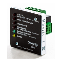
Operating & Installation Manual for the ES52 Engine Controller
Timer output. This output has one of four possible functions (Glow Plug, Smart Choke
TM
,
Air-Gate or Slow). This output closes to +12/24 VDC when activated.
Low Oil pressure output. Oil output closes to +12/24 VDC when the engine shuts down
due to a Low Oil pressure condition. Flashing Low Oil output indicates an Auxiliary Input
failure.
High Temperature output. Temperature output closes to +12/24 VDC when the engine
shuts down due to a high temp condition.
Over-crank output. Over-crank output closes to+12/24 VDC when the engine shuts down
due to an Over-crank failure.
Over-speed output. Over-speed output closes to +12/24 VDC on an Over-speed failure
and is open otherwise. Flashing output indicates Loss of Speed Signal.
Engine running output. Engine Running output closes to+12/24 VDC when the engine
speed is greater than the crank disconnect setting, and opens when the engine stops.
Flashing output indicates Crank Rest period.
Engine failure output. Engine failure output activates on any failure (closes to +12/24
VDC when activated).
Warmup output. Output turns on after the controller has been running for 2 minutes and
10 seconds. Output turns on immediately if battery voltage is applied to Start/Stop
(terminal 10) and the speed is greater than the crank disconnect pot setting when the
controller is not cranking.
Pins 12 to 19 Note
The maximum rating of each output depends on how many outputs are on simultaneously on pins 10 to
19. Do not exceed these values:
1 on = 300 mA, 2 on = 230 mA, 3 on = 160 mA, 4 on = 123 mA, 5 on = 91 mA, 6 on = 80 mA, 7 on =
66 mA, 8 on = 52mA.
Good practice is to use 50% of the maximum rating.
Common ground - For annunciation outputs only. DO NOT USE AS MAIN GROUND
TO CONTROLLER UNIT.
2.4 General Wiring Diagram
See next page for the wiring diagram and dimensions.
ATTENTION
All ES52 Controllers come with 12VDC Relays for 12V systems.
For 24V systems replace with 24VDC Relays.
ES52 Variant Note:
A diode across Auto and Start/Stop terminals is required on versions of the ES52 with the Cool-
Down feature (ES52 EI, FE, and LT variants). See the tech notes section at the end of this
manual for further information. The standard ES52 version does not require this.