Rev. 01/11 -1.16- TFXL-X
RATE PULSE OUTPUT CONNECTIONS
Connection of rate pulse output is simply a matter of connecting the
two field wiring terminals to the pulse input on the receiving
instrument and verifying that the K-factor is programmed into the
receiving instrument.
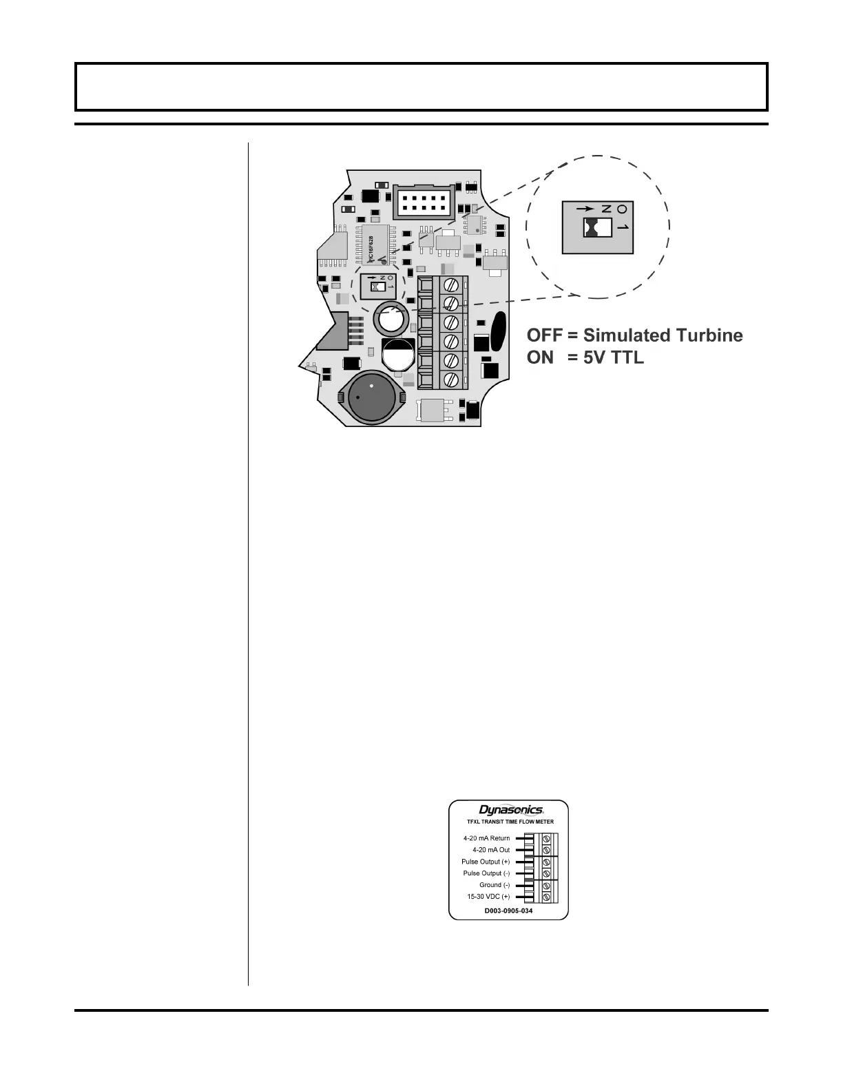
The simulated turbine output is not referenced to DC ground and is
not polarized, so wiring polarity is not important. See Figure 1.9.
The TTL output is referenced to DC ground and is polarized. When
using the TTL pulse, connect the plus (+) field terminal in the flow
meter to the frequency input on the receiving instrument. Connect
the negative (-) field terminal to the frequency input negative or DC
common connection in the receiving instrument. See Figure 1.9.
PART 1 - INPUT/OUTPUT CONFIGURATION
Figure 1.8
Rate Pulse Output Switch Positions
Figure 1.9
Pulse Output Field Wiring Connections
 Loading...

