22 23
Installation
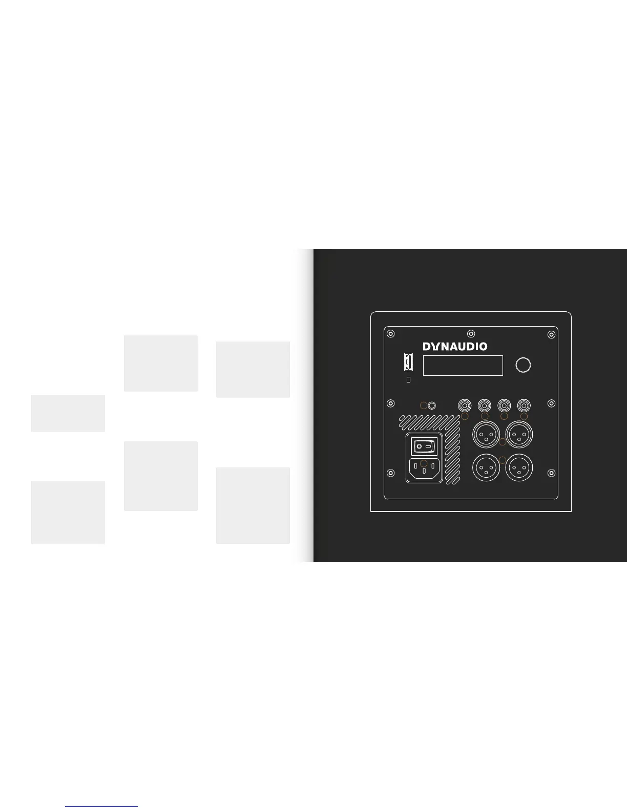
Sub6 Connection Sockets
Right
out
Right
in
Right
in
Left
in
Right
out
Left
out
Left
out
Left
in
Trigger
in
Service
Auto
ON/OFF
Max. 12 V DC
100-120 V~, 200-240 V~
50/60 Hz 490 W
6
5
5
1
4
4
3
2
Note
The USB socket present on
the Sub6 connection panel is
intended for fault diagnosis and
rmware update only. It cannot
be used for audio connection
or playback. Contact your
Dynaudio retailer or Dynaudio
directly for more information of
rmware updates.
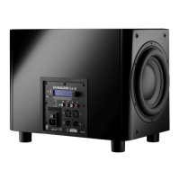
The Sub6 is tted on its rear face with
a connection and control panel carrying
mains, signal and connection sockets. The
panel is illustrated in Diagram 3 and its
connection facilities are described in the
following paragraphs. Diagrams illustration
various signal connection schemes can also
be found on the following pages.
Sub6 Mains and Signal Connections
2. Balanced XLR input sockets
(left and right). If your audio source
provides balanced outputs connect
them to these sockets using high
quality balanced XLR audio cables.
Note
Balanced signal connection
is a feature of professional
audio and of some high-end
domestic audio equipment. It
is inherently more resistant to
interference and noise than
unbalanced connection.
3. Balanced XLR output sockets (left
and right). The XLR output sockets
are intended for the connection of
active left and right main speakers,
a power amplier driving the main
speakers, or a second subwoofer.
Note
The Sub6 distance
compensation signal
processing can only function
correctly if the main speakers
are driven via the subwoofer
outputs.
4. Unbalanced phono input sockets
(left and right). If your audio source
provides unbalanced phono outputs
connect them to these sockets using
high quality phono audio cables.
Note
If your audio source provides
only a mono subwoofer
output it can be connected to
either Sub6 phono input. In
this case however the main
speakers must be driven from
the audio source and not via
the Sub6 outputs.
5. Unbalanced phono output
sockets (left and right). The phono
output sockets are intended for the
connection of active left and right
main speakers, a power amplier
driving the main speakers, or a
second subwoofer.
Note
The Sub6 distance
compensation signal
processing can only function
correctly if the main speakers
are driven via the subwoofer
outputs.
6. Trigger input. The trigger input
enables wired remote control of
subwoofer standby and operational
modes in automated home systems.
Your Dynaudio retailer or installer will
be able to provide more information
on the use of the Sub6 in home
automation systems.
1. Mains power socket. Connect the
subwoofer to a mains power supply
using the cable supplied. If multiple
cables are supplied with your
subwoofer, use the one appropriate
for your territory.
Note
Do not switch on your
subwoofer until all other
connections have been made.