Tower ESS Unit User Manual
20
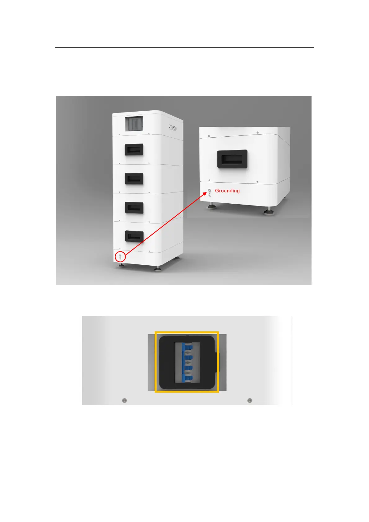
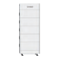
● After the HV9637 module is stacked up and down, it is fixed by two screws on the left and
right sides. After the screw is fixed, the shell surface of the upper and lower modules is fixed and
contacted together through screws.There is a special docking point at the bottom of the battery
base, as shown in the following figure, since the base has been on ground so its considered
grounded already, and the modules are connected with base, and they are all metal, so the
system is considered grounded without wire needed.
3.6.4 Battery system self-test
3.6.4.1 Switch the BDU“DC BREAKER”to the "ON" state
3.6.4.2 Switch on the “POWER ON” switch