From lab to production,
providing a window into the process
-15-
www.dynisco.com
Rev: n/aP/N: n/a ECO: n/a
Alarm Indicaon
The Acve Alarm Status screen indicates any acve alarms. In addion, the
associated Alarm LED ashes. For latching alarm outputs, the LED ashes when the
alarm condion exists,
and goes to ON when the alarm condion is no longer present if the output has not yet
been reset.
*Reseng Latched Alarm Outputs
Any latched outputs can be reset whilst the Process variable or Alarm Status screens
are displayed, by pressing the or key, via the Digital Input or with a
communicaons command via the RS485 module (if ed).
Note: Outputs will only reset if their alarm condion is no longer present.
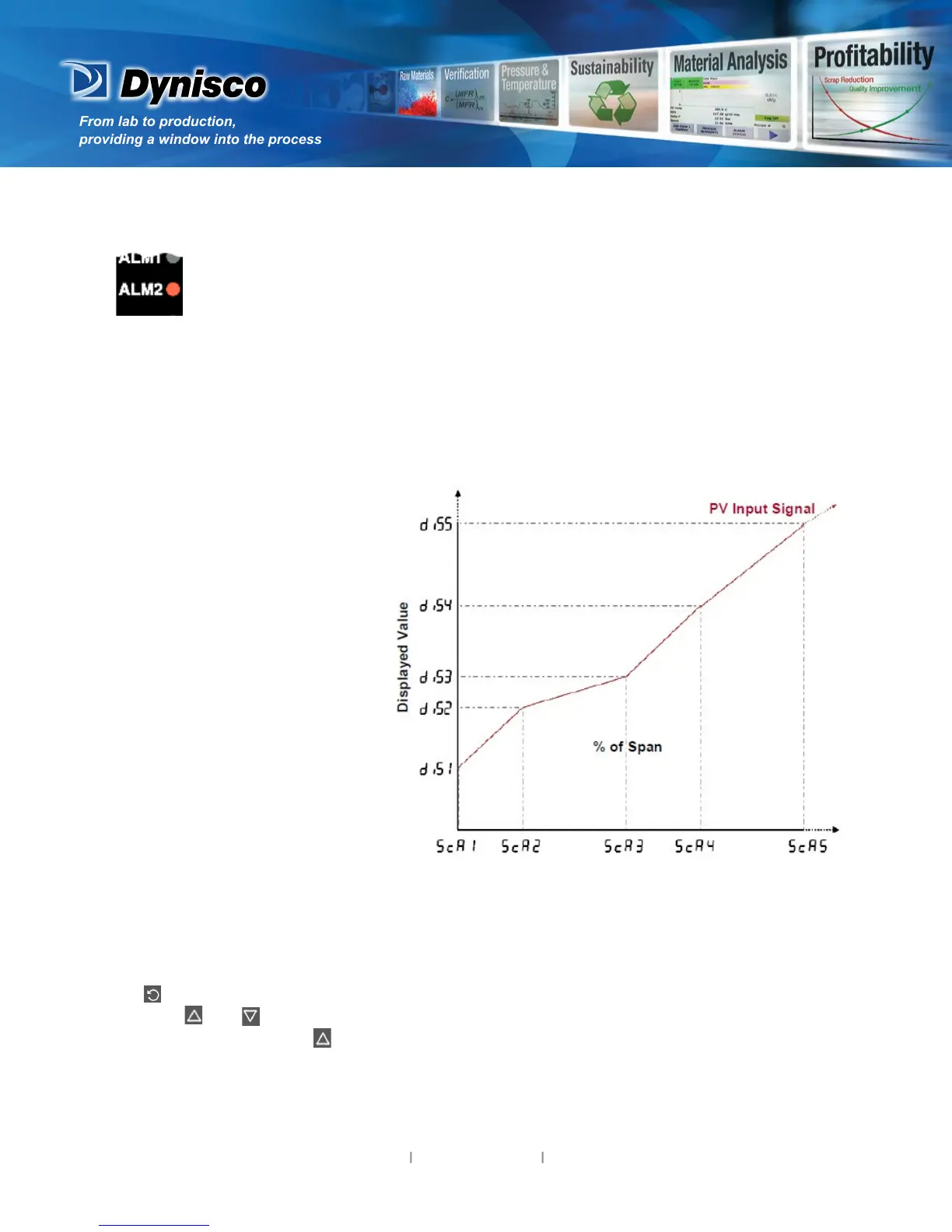
Mul-Point Scaling
When enabled (Mm PS =
EnAb), up to 9 breakpoints can
be set to compensate for nonlinear
input signals.
For each breakpoint, the input
scale value (ScALn) is entered in % of
input span, followed by the value to
be shown (diSPn) in display
units.
Each breakpoint’s input scale value
must be higher than the previous
value, but the display values can be
higher or lower. Any scale value set to
100% becomes the last in the series.
Tare Feature
When Tare is enabled (TARE = ENAB), it can be used to set the displayed value to zero automacally,
by making the PV Oset parameter equal, but opposite to, the current process variable value. Tare
can be iniated via the Digital Input (if ed), with a communicaons command via the RS485
module (if ed) or by using the following key press sequence:
Press unl the process variable is displayed.
Hold down and together for three seconds unl the display shows YES?
Release both keys and press within 3 seconds to conrm the request.
The display should read 0 briey, then begin responding to input signal changes. This will have no
eect on any stored Max or Min values unl they are reset. Once Reset the Max and Min value will
follow the displayed value that has gone through the tare process
Note: Tare request is aborted if this sequence is not followed exactly.
 Loading...

