From lab to production,
providing a window into the process
-2-
www.dynisco.com
Rev: n/aP/N: n/a ECO: n/a
CAUTION: Installaon should be only performed by technically competent personnel.
Local Regulaons regarding electrical installaon & safety must be observed. The host
equipment is required to provide a suitable electrical, mechanical and re enclosure to
meet relevant safety standards. Impairment of protecon will occur if the product is
used in a manner not specied by the manufacturer.
CAUTION: All power supply connecons to the device must be removed
when carrying out any form of maintenance.
1. Installaon
Installing Opon Modules/Maintenance
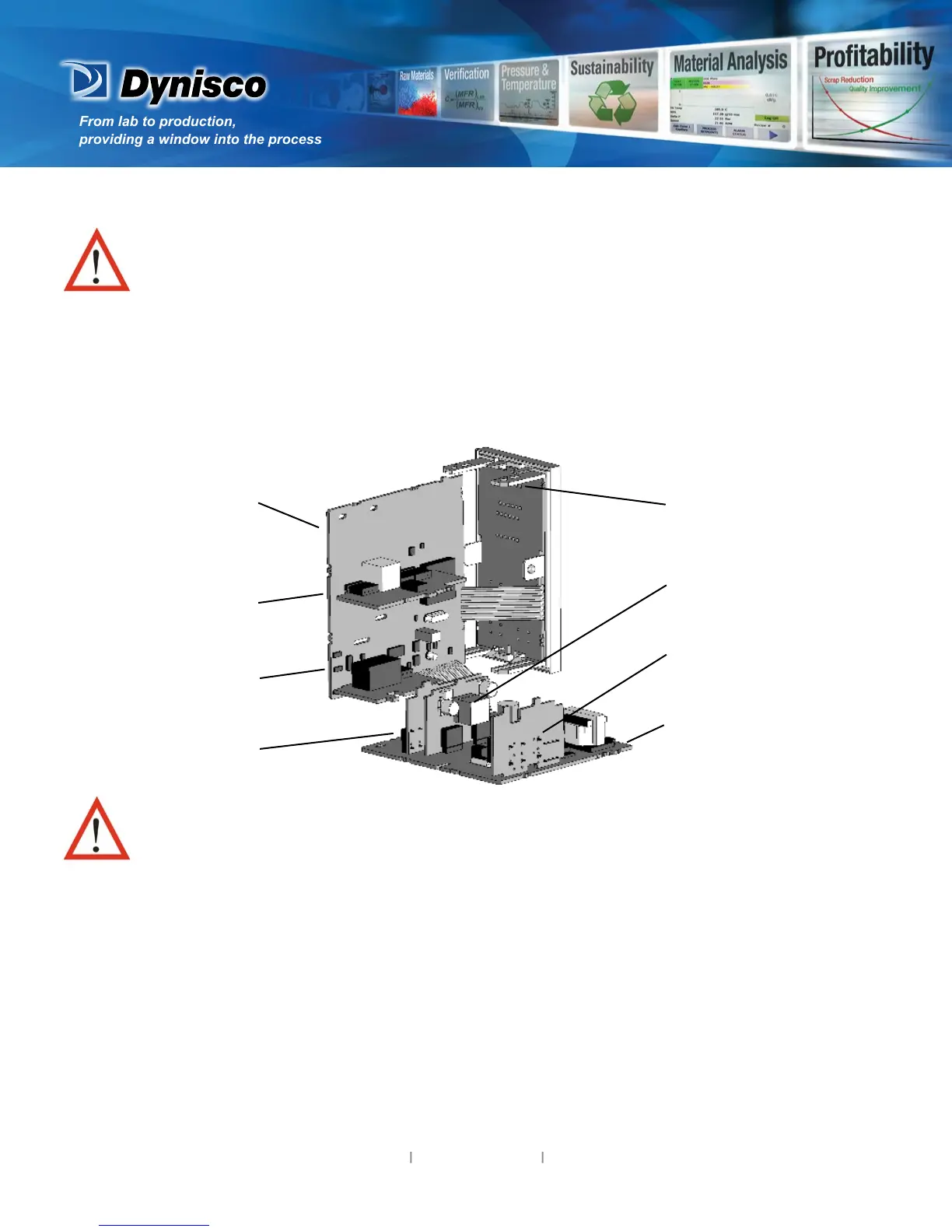
CPU PCB
Future Opon
Opon Module 2
Opon Module 1
Mounng Sturts
Opon Module A
Opon Module 3
PSU PCB
To access modules, rst detach the PSU and CPU boards from the front by liing rst
the upper, and then lower mounng struts. Gently separate the boards.
a. Plug the required opon modules into the correct connectors, as shown below.
b. Locate the module tongues in the corresponding slot on the opposite board.
c. Hold the main boards together while relocang back on the mounng struts.
d. Replace the instrument by aligning the CPU and PSU boards with their guides in the housing, then
slowly push the instrument back into posion.
NOTE: Opon modules are automacally detected at power up.