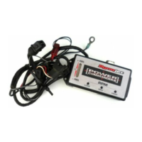
7 Unplug the Throttle Position
Sensor from the the throttle
body (Fig. D).
8 Crimp the supplied wire tap to
the yellow wire (#2 position) of
the TPS harness (Fig. E).
9 Connect the GREY wire from
the PCIII to the wire tap.
Note: It is recommended to use dielec-
tric grease on these connections.
10 Plug the TPS connector back
onto the throttle body.
Fig. D
2006 Yamaha MT03 - PCIII USB - 3i422-411 www.powercommander.com
Fig. E
Grey wire from PCIII
Wire tap
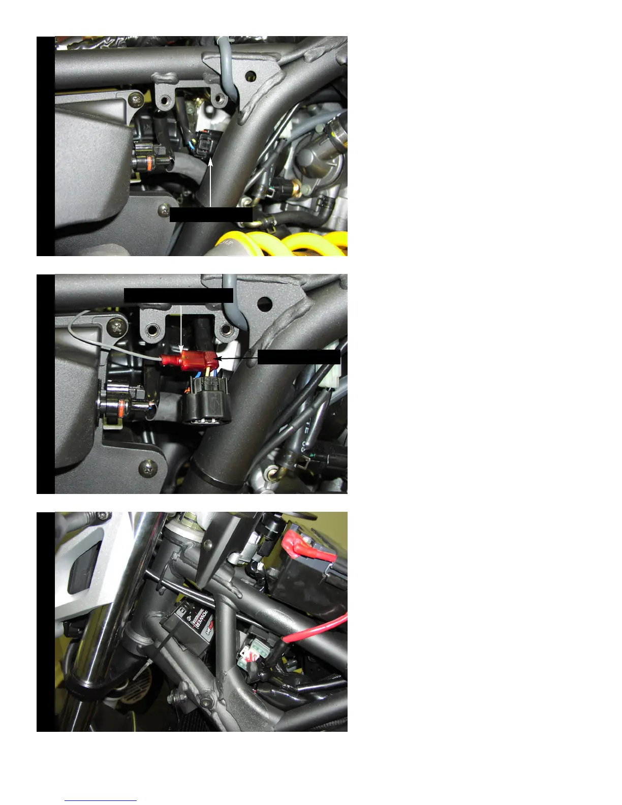
Fig. F
11 Reinstall the map sensor to the
frame.
12 Attach the ground wire of the
PCIII to the negative side of the
battery.
13 Install the PCIII to the frame
using the supplied velcro.
Secure the PCIII using the sup-
plied zip tie (Fig. F).
14 Bolt the fuel tank back into
place making sure it does not
pinch the PCIII harness.
Unplug TPS

 Loading...