16-044 www.powercommander.com 2009-2013 Honda Goldwing/FB6 - PCV - 9
29 Locate and unplug the stock connector for the left O2 sensor (Fig. T).
This is located on the left side of the frame. It is a BLACK 4-pin connector.
FIG.T
Unplug
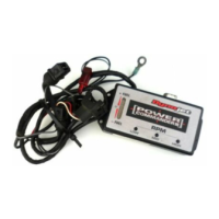
30 Plug the supplied O2 Optimizer (with male pins) into the stock wiring harness
in place of the stock O2 sensor (Fig. U).
The stock O2 sensor will no longer be used. It can be removed from the
exhaust, if desired and if you have a way to plug the hole.
31 Reassemble the bike.
Note: The modules will be difficult to access after the bodywork is reinstalled. The
glove compartments on both sides would need to be removed to access the
modules. You can leave the usb cables connected to the modules and routed
to the inside of the glove compartments, if you prefer.
To see a video of this installation, visit our channel (DynojetResearch)
on YouTube.
FIG.U
 Loading...