16-044 www.powercommander.com 2009-2013 Honda Goldwing/FB6 - PCV - 8
25 Plug the pair of matching connectors on the SFM harness in-line with the stock
connectors.
26 Locate and unplug the stock connector for the right O2 sensor in this same
connector bundle (Fig. Q).
This is also a BLACK 4-pin connector, except this one should have 2 WHITE
wires, a BLACK, and a GREY wire.
FIG.Q
27 Plug the supplied O2 Optimizer (with female pins) into the stock wiring
harness in place of the stock O2 sensor (Fig. P).
The stock O2 sensor will no longer be used. It can be removed from the
exhaust, if desired and if you have a way to plug the hole.
FIG.R
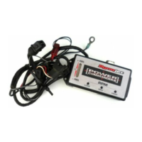
28 Secure the SFM ground wire with the 6mm ring lug to bolt on the rear of the
right intake manifold (Fig. S).
FIG.S
Unplug
Ground

 Loading...