25-010 www.powercommander.com 11-12 CanAm Spyder RT PCV - 8
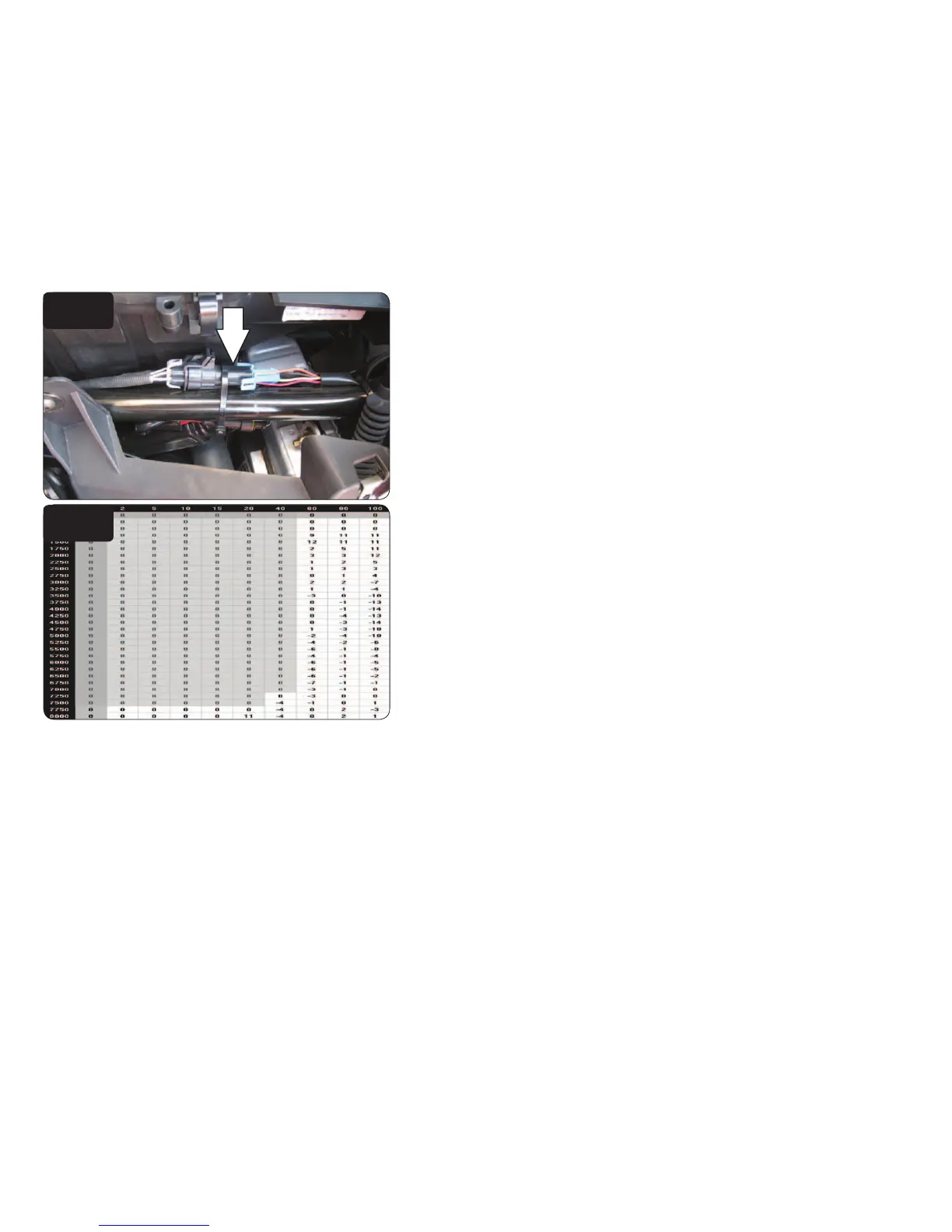
FIG.Q
FIG.R
The O2 optimizer for this model controls the stock closed loop area. This area
is represented by the highlighted cells shown in Figure R. The optimizer is
designed to achieve a target AFR of 13.6:1. To use this optimizer you must
retain your stock O2 sensors.
It is not recommended to alter the values in the highlighted area unless
instructed to do so by a Dynojet technician. Usually a value of 8-10 is best.
If using the Auto tune system do NOT input values in this area in your Target
AFR table.
26 Unplug the stock wiring harness from the rear O2 sensor (Fig. Q).
This connection is located on the right side of the vehicle between the air box and
the frame rail.
27 Plug the 4 pin connector from the O2 Optimizer labeled REAR in-line of the
stock O2 sensor and wiring harness.
28 Reinstall bodywork.