EasyManuals Logo

Dynojet POWER COMMANDER User Manual

Dynojet POWER COMMANDER
6 pages
To Next Page IconTo Next Page
To Previous Page IconTo Previous Page
Page #4 background imageLoading...
Page #4 background image
18-023 www.powercommander.com 17-18 RC/Duke 390 - PCV - 4
FIG.F
FIG.D
FIG.E
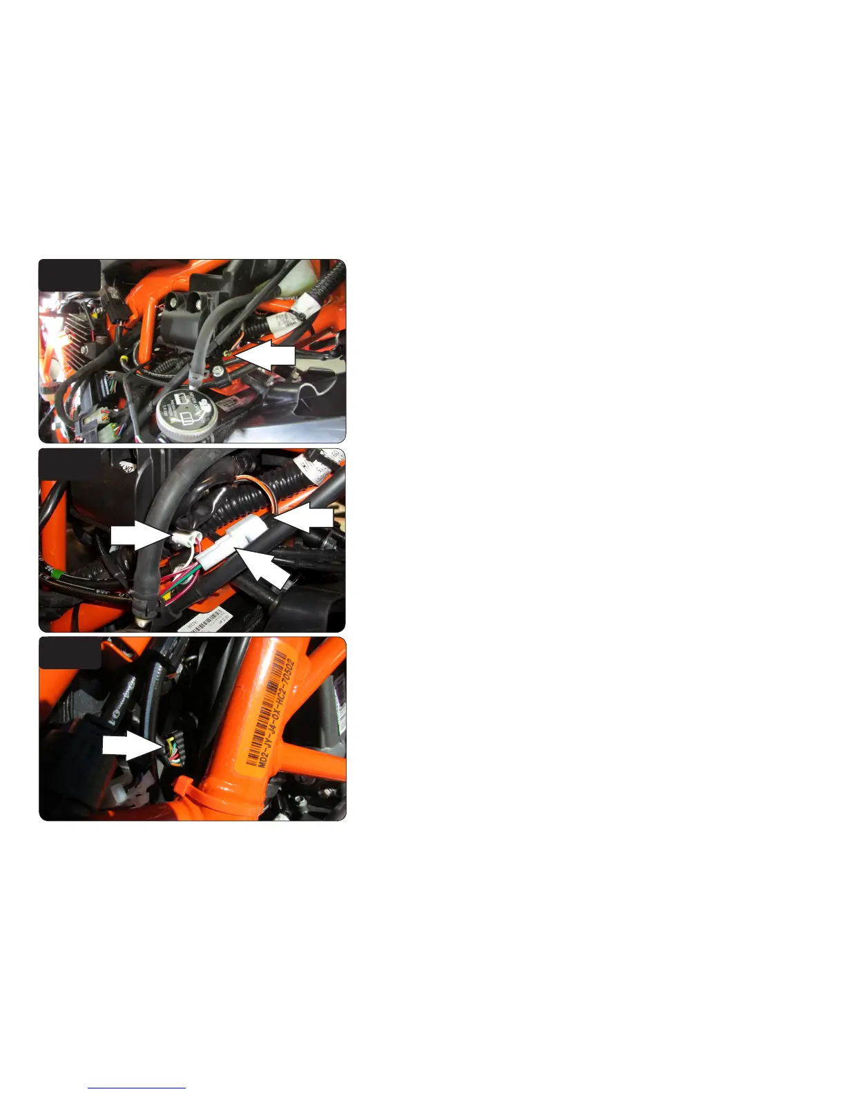
8 Unplug the stock wiring harness from the ignition coil (Fig. D).
This is a BLACK, 2 pin connector on the right hand side.
9 Plug the PCV in-line of the stock wiring harness and stock ignition coil (Fig. E)
10 Unplug the stock Throttle Position Sensor connector (Fig. F).
This is a BLACK, 6 pin connector on the RH side of the throttle body.
11 Plug the PCV in-line of the stock TPS and wiring harness.
Unplug
Unplug
Stk
PCV
PCV

Questions and Answers:

Question and Answer IconNeed help?

Do you have a question about the Dynojet POWER COMMANDER and is the answer not in the manual?

Dynojet POWER COMMANDER Specifications

General IconGeneral
BrandDynojet
ModelPOWER COMMANDER
CategoryMotorcycle Accessories
LanguageEnglish

Related product manuals