EasyManuals Logo

Dynojet POWER COMMANDER User Manual

Dynojet POWER COMMANDER
6 pages
To Next Page IconTo Next Page
To Previous Page IconTo Previous Page
Page #5 background imageLoading...
Page #5 background image
18-023 www.powercommander.com 17-18 RC/Duke 390 - PCV - 5
FIG.G
FIG.H
FIG.J
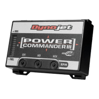
12 Unplug the wiring harness from the fuel injector (Fig. G).
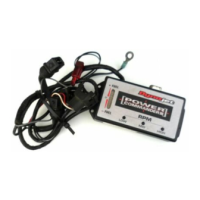
13 Plug the PCV in-line of the stock fuel injector and wiring harness (Fig. H).
14 Route the PCV harness as shown in Figure H and secure to the frame using
the zip tie.
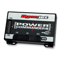
15 Unplug the stock crank position sensor connector (Fig. J).
This is a WHITE, 6 pin connector near the FRT, LH side of the cylinder head.
Unplug
PCV harness
Unplug

Questions and Answers:

Question and Answer IconNeed help?

Do you have a question about the Dynojet POWER COMMANDER and is the answer not in the manual?

Dynojet POWER COMMANDER Specifications

General IconGeneral
BrandDynojet
ModelPOWER COMMANDER
CategoryMotorcycle Accessories
LanguageEnglish

Related product manuals