5
INSTALLATION CONTINUED
2 Install both of the supplied 18mm wideband O2 sensors into the exhaust system. Refer to “O2 Sensor Bung Installation”
for guidelines if 18mm x 1.5 bungs need to be welded.
3 Connect an O2 sensor cable to the front cylinder O2 sensor and route harness along the frame or stock wiring harness
going towards the Target Tune module.
4 Connect the other O2 sensor harness to the rear cylinder O2 sensor and route harness along the frame or stock wiring
harness going towards the Target Tune module.
Note: Keep harnesses away from HOT and/or moving parts to prevent damage.
Note: If the supplied cables have different lengths, the longer cable should go to the front cylinder.
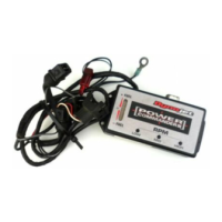
5 Connect the front cylinder O2 sensor harness to Target Tune module input #1 as shown.
6 Connect the rear cylinder O2 sensor harness to Target Tune module input #2 as shown.
Note: The harness can be cut to length if desired.
Note: To make inserting the wires into the module easier, fi rst poke the hole with a paperclip or similar device.
Also tinning the bare wire ends with solder can help.
7 Locate and unplug the stock O2 sensor connections. You can trace the cables from the stock O2 sensors in the exhaust to
these connectors.
8 Plug the connectors from the Target Tune into the stock O2 sensors connectors.
Plug the Target Tune lead with the YELLOW/ORANGE wire into the FRONT cylinder stock O2 connector.
Plug the Target Tune lead with the YELLOW/GREEN wire into the REAR cylinder stock O2 connector.
Note: The stock O2 sensors will no longer be connected to anything and can be removed from the exhaust if desired
and if you have a way to plug the holes in the exhaust.
To Power Vi sion
To Veh icle
Diagnostic Cable To Power Vision 3
76951056 Cable with CAN Connector
NOTE: Do NOT plug CAN connector into Target Tune.
Yellow/Green
Yellow/Orange
STOCK O CONNECTOR
2
(FRONT)
STOCK O CONNECTOR
2
(REAR)
O SENSOR
2
O SENSOR
2
FRONT
REAR