35
M
5
Ø
3
5
.0
82.0
3
4
.
0
1
0
6
.
0
1 2
3
4
5 6
max. 4 mm
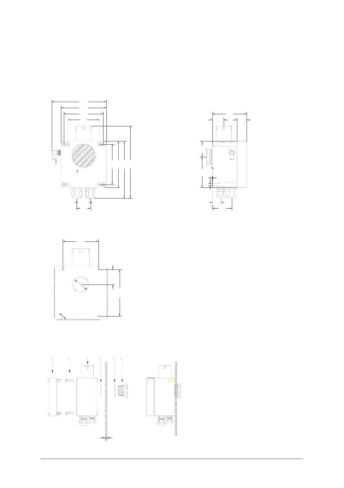
6.2.1.1 Mounting the Monitoring Unit
For external mounting on an enclosure, holes must be drilled for the digital/proportional
valve/air inlet, the air outlet and the mounting holes for the monitoring unit.
Any mounting position is possible, but ensure that the display is easy to read.
Fig. 9: Dimensions of the controller F-351
Fig. 9a: Drilling plan to mount controller on cabinet
1 Cover F-351
2 Mounting screws 4x M5x20
3 F-351 housing
4 Sealing 33,7 x 2,2 mm
5 Sealing 33,7 x 3,5 mm
6 Inlet screw with hole 1"
Fig. 10: Mounting of F-351
6
.
5
8
0
.
0
30.0 25.0
90.0
0.5
4
2
.
0
air inlet screw R1"
23.0
51.0
82.0
104.0
120.0
144.0
1
0
6
.
0
30.0
37.0
1
2
2
.
0
1
5
0
.
0
1
9
0
.
0
in
t
r
in
s
ic
s
a
f
e
c
o
n
n
e
c
t
o
r
security glass
 Loading...