CLASS 3200 METER
62-0390-02 18
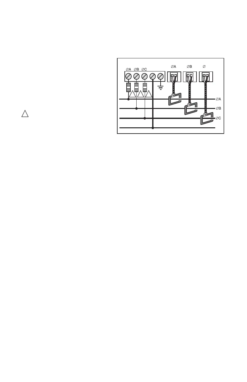
6.5 Main Power & Current Sensor Wiring Diagram
Fig. 8. 3-phase- 4 Wire Installation Diagram
6.6 Line Voltage/Current Sensor Diagnostics
Following is a list of diagnostic messages that may appear on the meter display.
DIAGNOSTIC MESSAGES SHOULD NOT BE ON CONTINUOUSLY WHEN THE
METER IS INSTALLED PROPERLY AND IS IN WORKING ORDER.
6.6.1 Line Voltage Diagnostics
The diagnostics program detects line voltage faults by displaying one of two
messages:
PH Missing: B C or Phase sequence error.
Phase sequence error
indicates that the 3-phase line voltage is not hooked up in the
proper phase sequence. This message should never be seen continuously on the
display during normal operation. The meter will not display correct electrical data in
this condition. The phase sequence problem must be remedied in order for the meter
to work properly.
Missing: B C
indicates that the line voltage is missing on Phase B and/or Phase C.
This message will appear whenever the power on either Phase B or Phase C is off.
Screen 5 (Voltage per Phase) will also indicate a loss of line voltage.
LINE VOLTAGE
CURRENT SENSORS
N
LOAD SOURCE
M33185
3-PHASE, 4-WIRE INSTALLATION DIAGRAM
NOTES:
LINE VOLTAGE CONNECTIONS: #14-12 AWG
SENSOR CONNECTIONS: B = BLACK LEAD W = WHITE LEAD
NEUTRAL NOT USED IN DELTA SYSTEM. REMOVE NEUTRAL TERMINAL
BLOCK SCREW FOR DELTA SYSTEMS.
1/10A 600 VAC INLINE FUSE PER CONDUCTOR. LITTLEFUSE PART
NUMBER KLDR.100.
1
1
1
1
C
W B W B
N
PE
W B