13
3.3. Noting the serial numbers
Each PowerPlex
®
component has a unique serial number. Before mounting the PowerPlex
®
modules, we
recommend to prepare a list. This list should include: PowerPlex
®
component (module type), pertinent serial
number and installation area.
You find the serial number of the PowerPlex
®
WS300 on the label attached to the housing. The serial number
consists of 7 letters and numbers. It is used as an identification for new, not yet projected modules which have the
CAN bus address “0” for a start. The serial numbers are required for system set-up. By means of the PowerPlex
®
configuration software the pertinent CAN bus addresses will be assigned.
Information
Please note the 7-digit serial number of each PowerPlex
®
component. It is required for the subsequent
system configuration with the PowerPlex
®
configuration software.
Later, when you start configuring the modules and when you define their roles in the CAN network, the assignment
between serial number, CAN bus address and installation area must be made.
The use of CAN bus address labels helps keeping an overview for module identification, above all in the event of
comprehensive projects.
3.4. The module CAN bus address
Every PowerPlex
®
component within a PowerPlex
®
network has its own unique CAN bus address in a range of
1 to 30 for a clear identification. Assignment of the CAN bus addresses is during the system set-up by means of
the PowerPlex
®
Configuration Software.
We recommend to mark the modules in the PowerPlex
®
system with the corresponding module CAN bus
addresses so as to be able to keep track.
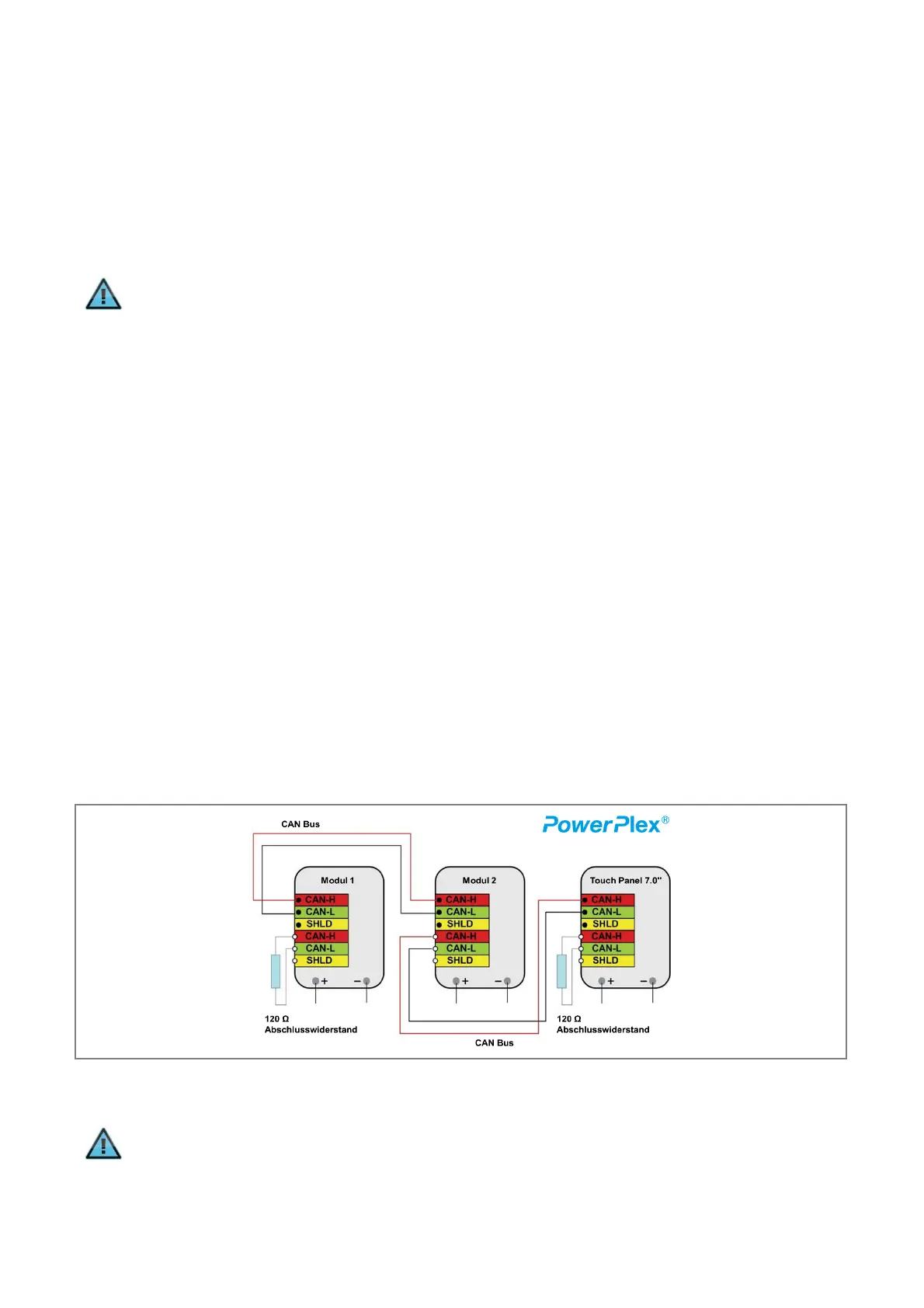
3.5. Integration in the CAN bus network
To set up the CAN bus network all PowerPlex
®
components are connected with each other (→ Fig. 6).
A CAN bus must be terminated with a 120 Ω resistor at the beginning and end of the bus. Terminating resistors
are not installed in the PowerPlex
®
modules. For modules that are the first or last participant on the CAN bus, a
120 Ω terminating resistor must be placed in the free CAN H and CAN L pin or the cage clamp terminal.
Fig. 6: Connection of the PowerPlex
®
components in the CAN bus system
Information
The terminating resistors are not included in the scope of delivery They can be ordered separately as
accessories.