19
All cables are connected to the module from below. This has to be considered in the planning stage and ensures
ease of mounting, preventing a possible kinking of the cables.
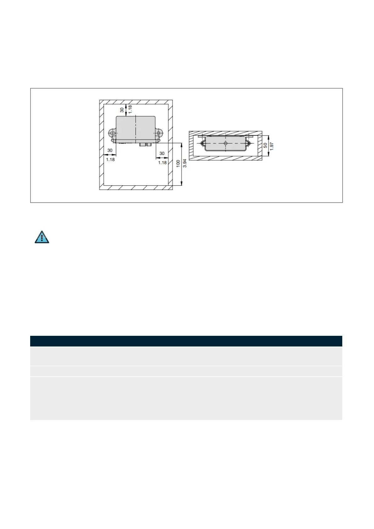
5.5. Dimensions and space requirements
According to EMC conditions there must always be sufficient space between the different electrical devices. Space
requirement of a device depends on its dimensions shown in Fig. 10.
Fig. 10: Installation dimensions of the PowerPlex
®
Web Server WS300
Information
The protection class IP22 is achieved when the PowerPlex
®
Web Server WS300 is installed vertically
with the terminals pointing downwards.
5.6. Mounting of the device
Before you start installation, please make sure that
• the installation site was selected under consideration of the product-specific requirements
• the cable connections were identified correctly and cable laying was thoroughly planned
• the power supply was disconnected and protected against inadvertent reset
Mark the intended installation site following the installation dimensions. Mark the position for the used
wall mounting bracket.
Drill the mounting holes into the wall with an adequate tool.
Depending on the accessibility of the cable connections it could be useful to connect all cables (current,
CAN etc.) before mounting the device.
Important: A cable connection must only be established if the main switch is OFF. Check the cables
with regard to correct polarity and ensure that the max. permissible operating voltage is not exceeded.
Please do not forget the terminating resistor if the device is the first or last participant on the CAN bus.
Table 8: Mounting of the device