14
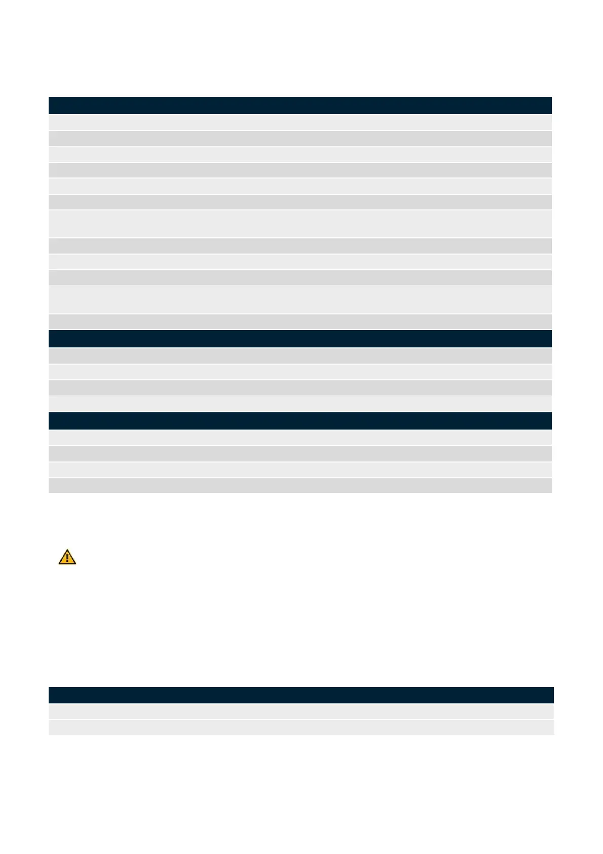
A CAN bus cable typically is a twisted pair cable with two wires, CAN-H and CAN-L, and shield SHLD. Table 3
lists the most important properties which the CAN bus cable to be used should have. They correspond to a typical
CAN bus cable.
Diameter - inner conductor
multi-stranded copper conductor
laid out: 90 mm
static: 48 mm
-40 °C … +70 °C (-40 … +158 °F)
Resistance against ambient effects
UV resistant, weatherproof, oil-resistant, coolant-resistant, microbe-resistant
abrasion-proof, notch-resistant, low adhesion
Table 3: Major properties of the CAN bus cable to be used
*) Fa. Helukabel: CAN.BUS 1X2X0.50, www.helukabel.de
Caution
Please make sure that beginning and end of the CAN bus network are closed off with a 120-Ω resistor.
Both the first and the last PowerPlex
®
component must have a 120-Ω terminating resistor. This is of
major importance for the correct and reliable function of the PowerPlex
®
installation.
3.6. PowerPlex
®
System Undervoltage Protection
The PowerPlex
®
system is fitted with undervoltage protection. If the supply voltage (battery voltage) drops below
a certain value (as shown in Table 4) all load outputs will be disconnected. This feature ensures a stable voltage
range in which the system can work.
PowerPlex
®
system response
disconnection of all load output
Table 4: Undervoltage protection and operating voltage range