13
AVI Slide Rev - C
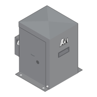
Power Fail Operation
Radio Receiver
Power Fail Operation
Make sure power is turned OFF on operator
BEFORE inserting hand crank.
Insert hand crank into hole and rotate to move gate.
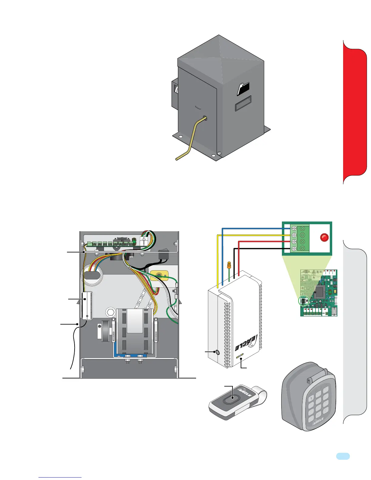
Radio Receiver Installation and “Learning” Remote Button
The radio receiver is wired to the control board #1 as shown.
Eagle offers a
wireless keypad.
Sold separately
1. Press and release button on the receiver. LED will turn red.
2. Press button on remote twice and the LED will flash and turn back to green.
3. Repeat steps for other desired remote buttons.
4. To delete all remotes, hold the receiver program button for 8 seconds.
5. The EG650 receiver has a maximum capacity of 30 remotes.
Optional: EG652 receiver has a maximum capacity of 300 remotes.
GND
GND
RCVR
24VAC
#1
RECEIVER
Control Board Connection #1
Blue
Black
Red
Yellow
NOTE: Radio Receiver can be connected to the master or slave o
erator for master/slave installation.
PO
WE
RED
BY EAGL
E
AV I
Hand Crank
(5/16” Allen Wrench)
LEARN Remote Button
Radio Receiver
Location
Receiver
Program
Button
Remote Button
Green wire
not used.
LED
Run wires
through hole
in plate.
Run antenna
through hole
to increase
wireless range.
Radio
Receiver
Eagle Part
Number:
EG650
Remote
2
5
8
0
1
4
7
A
3
6
9
B
Eagle Wireless Keypad
Eagle Part Number: EG654
ERD CONTROL
MULTI FUNCTION
GATE STATUS
CLOSING
OPEN
LIMIT
OPENING CLOSING CLOSED
LIMIT
SLAVE MASTER
+ – + –
#9#8
+ MAGLOCK
- 24 VDC
#5
+ ALARM
- 12 VDC
#6
REVERSE
LOOP
#2
POWER
24VAC
#7
KEY
#3
M-FCN
#4
GND
GND
RCVR
24VAC
#1
COMM PORTINPUT/OUTPUT
RECEIVER
ON ON STOP N/C
OFF ON PHANTOM
OFF OFF EDGE SENSOR
COMM PORT POWER
RD
NTR
L
LTI F
N
TI
N
CLOSING
N
N
T
P N
FF
N PHANT
M